

Introduction: Configuring and Testing Bluetooth Modules


This Instructable is a step in the process of creating a Camera Surveillance Kit. The next step in the process is learning how to configure a Camera Module.
This tutorial includes information on how to configure HC-05 Bluetooth modules for data transmission and how to test the module using a button to turn an LED on and off.
Supplies
Before beginning, ensure that you have selected the correct HC-05 Bluetooth Module for use. Others, including the HC-06 Slave-only device and HC-07 iOS compatible device may not have the same commands as given in this tutorial. Additionally, many HC-05 modules such as the one given here have their own AT Commands (e.g. Do not have the AT+BIND function, return different responses to AT+UART, and use AT+ROLE=M or S instead of 1 or 0. Contact your seller for the datasheet and a list of available commands).
- Two HC-05 Bluetooth Serial Communication Modules for Arduino: https://www.amazon.ca/gp/product/B01M248TJU/ref=pp...
- Two Arduino Uno R3s: https://www.amazon.ca/Elegoo-Board-ATmega328P-ATME...
- Male to Female and Male to Male Jumper Wires: https://www.amazon.ca/gp/product/B01EV70C78/ref=pp...
- Resistor Pack: https://www.amazon.ca/gp/product/B073ZC6SF9/ref=pp...
- LED Pack: https://www.amazon.ca/Gikfun-Assorted-Arduino-100p...
- NO (Normally Open) SPST (single pull, single throw) Pushbutton: https://www.amazon.com/Gikfun-12x12x7-3-Tactile-M...
- 9V Battery
- DC Jack Connector for Arduino: https://www.amazon.com/5pack-Battery-2-1mm-Arduin...
Step 1: Setting Up the AT Command Mode
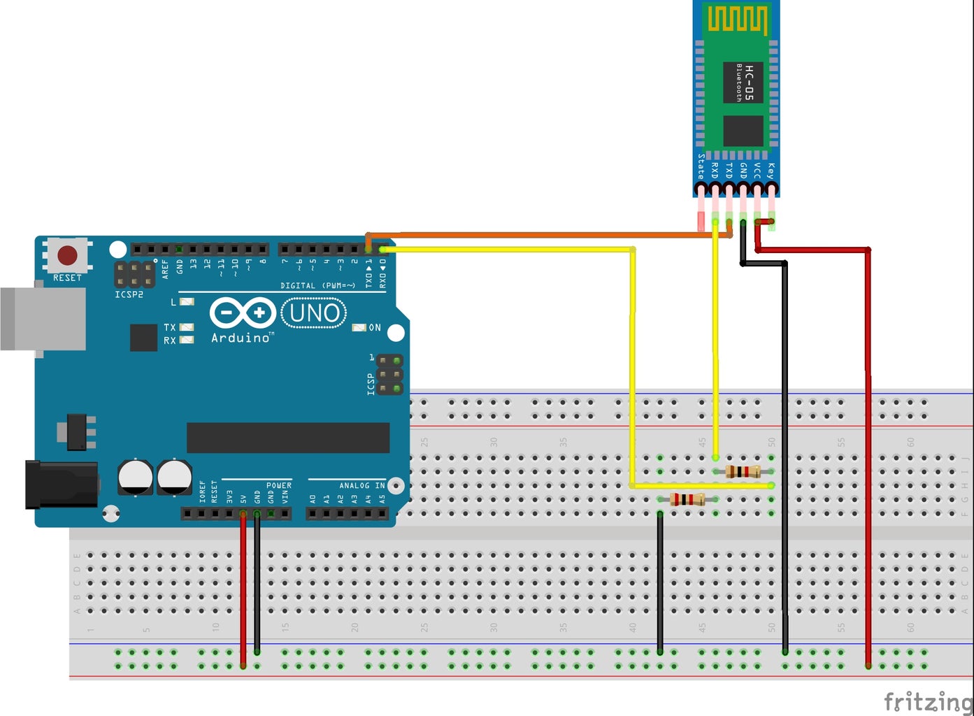
To begin setting up the bluetooth module, we must first configure a few of its settings by connecting it in the "AT Command Mode" as shown:
- HC-05 RX to Arduino RX Pin 0 via the voltage divider circuit shown
- HC-05 TX to Arduino TX Pin 1
- HC-05 VCC to Arduino 5V VCC
- HC-05 GND to Arduino GND
- HC-05 EN Pin to HC-05 VCC Pin
Note that the "EN" pin may sometimes be referred to as "KEY", though functionality is generally the same. Once you connect the module in this setup, its onboard LED should begin blinking slowly every 2 seconds (if you have purchased the one shown in the parts list). If this is unsuccessful, try disconnecting and reconnecting the VCC and GND cables to reset the module.
Ensure that you connect the RX/TX pins only via the voltage divider as shown. Otherwise, the pins of the HC-05 could become permanently damaged, or could result in the HC-05 not sending and receiving commands correctly.
The voltage divider consists of a connection from the given Arduino pin to a 1k ohm resistor that connects to a junction with the HC-05's given pin and a 2k ohm resistor. The 2k ohm resistor then connects to ground. Note the resistor colour codes as shown in the schematic diagram.
Once you have connected the circuit as shown, connect your Arduino to your PC using the upload cable, and upload an empty sketch to your Arduino board as in the attached file.
When connecting the module to your Arduino, be sure to disconnect the wires attached to the Arduino's RX and TX pins, since the board uses these to upload code.
Step 2: Configuring the Slave Device With AT Commands

(Image credits to Educ8s.tv)
Now that we've connected our HC-05 to be programmed, we will ensure that it has the correct role so that it can connect to our testing devices. The HC-05 can either be in the "Master" or "Slave" state. The Master role allows the module to actively connect to another device, while the slave mode simply makes it discoverable to other devices. Note that this has nothing to do with which device can send or receive data, since both modules are transceivers (both transmitters and receivers). It simply toggles between a device's ability to be discovered by or actively discover other devices.
To begin using the AT commands, open the Serial Monitor, and set the baud rate to 38400 - the standard communication rate for HC-05 modules. Set the line ending to "Both NL and CR".
Type "AT" into the terminal and press enter. If you see a message that says "Error" or "OK", you have connected the module correctly, and are ready to send commands!
To begin, let's try changing the name of the module to ensure we know we've connected to the right one. You can use the command "AT+NAME?" to first figure out the name of the module, which will often be "HC-05" or something similar when first used. Change the name by entering the command "AT+NAME=HC-05 Slave". If the response is "OK", the command was successful.
Now, before we change the role of the module, we must ensure its communication rate is the same as the other module we will be pairing it with. Enter the command "AT+UART?" to check the baud rate of the module. The returned response will include three separate integers, with the first being the baud rate. For most devices, the default is 38400, but it is generally simpler to keep the device working at 9600 baud. To set a new communication rate, enter the command "AT+UART=9600,0,0". The response should be "OK". Send the command "AT+RESET" to save these changes, and reconnect the device to change the baud rate. Remember to change the baud rate in the Serial monitor before trying to enter more commands!
Now, to set the device in slave mode, begin by entering the command "AT+ROLE?" to check its current role. If the device returns "+ROLE=0", the module is set in Slave mode (it should be, by default). Otherwise, if it is currently in the "1", or Master state, enter the command "AT+ROLE=0" to set it to Slave mode. The response should be "OK".
In addition to changing the role, we will soon need the device's MAC address to connect it the other bluetooth module via the Arduino securely. To retrieve this information, enter the command "AT+ADDR?". The serial monitor should return a string of characters separated by colons. Copy this address and store it for later.
Summary of commands:
Enter: AT
Response: OK
Enter: AT+NAME?
Response: HC-05
Enter: AT+NAME=HC-05 Slave
Response: OK
Enter: AT+UART?
Response: +UART: 38400, 0, 0
Enter: AT+UART=9600,0,0
Response: OK
Enter: AT+RESET
Response: OK
Enter: AT+ROLE?
Response: +ROLE:0
Enter: AT+ROLE=0
Response: OK
Enter: AT+ADDR?
Response: +ADDR:01a2:b3:c4d5e6f
Step 3: Connecting the Module in Transceiver Mode
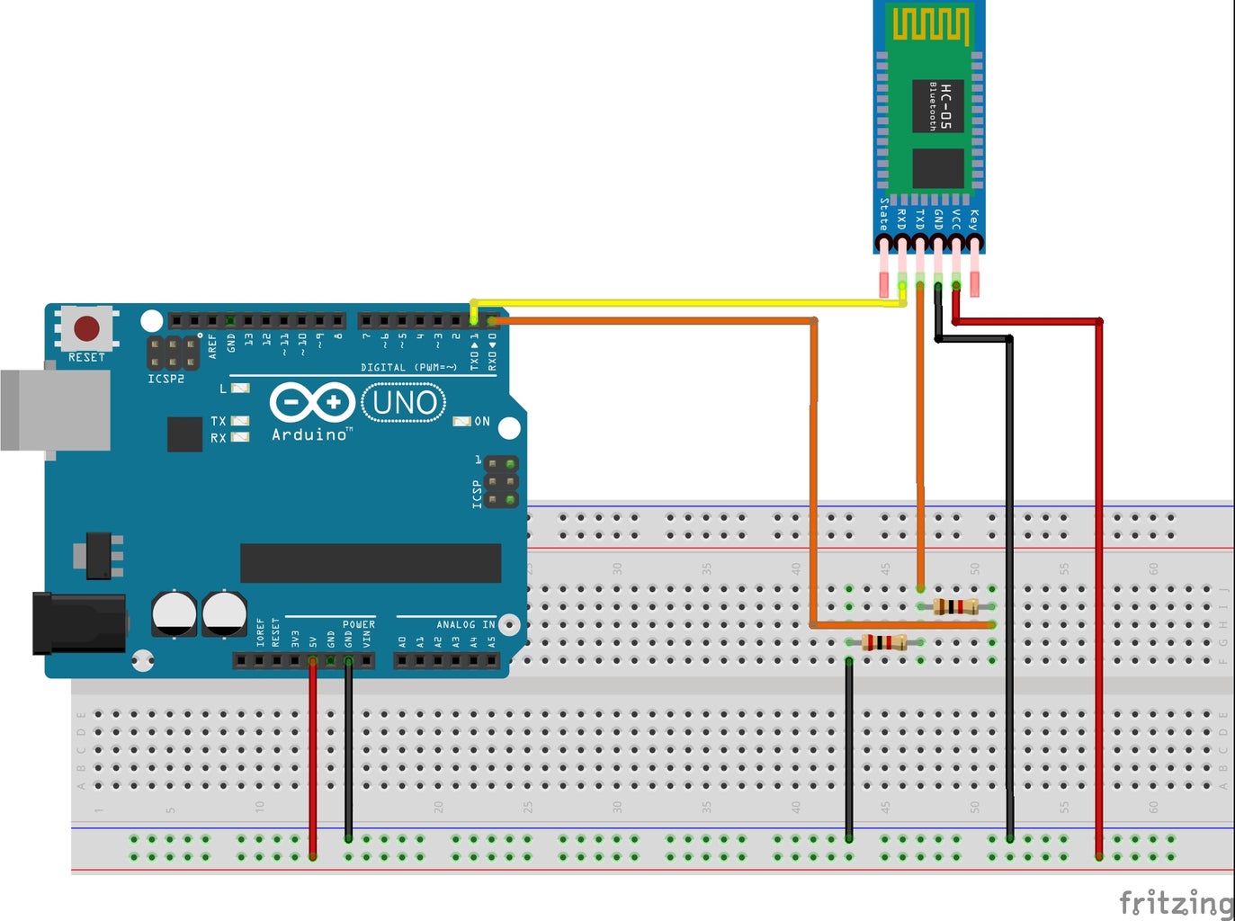
To connect the bluetooth module in the "normal" transceiver mode, simply switch the TX and RX pin connection such that the RX pin of the HC-05 connects to the TX pin of the Arduino via the voltage divider, and the TX pin of the HC-05 connects to the RX pin of the Arduino.
Connection Summary:
- HC-05 RX to Arduino RX Pin via the voltage divider circuit shown
- HC-05 TX to Arduino TX Pin
- HC-05 VCC to Arduino 5V VCC
- HC-05 GND to Arduino GND
- HC-05 EN Pin to HC-05 VCC Pin
Once this has been completed, the Arduino is ready to be programmed. This circuit will have an indicator LED that will turn on or off depending on the state of the detected value.
Step 4: Connecting and Programming the Indicator LED
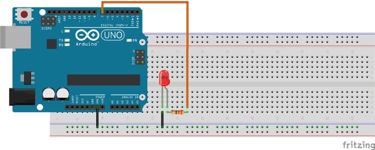
The indicator LED can be connected to the Arduino via pin 7 as the voltage source, through a 330 ohm resistor (to ensure the LED does not blow out), and out to the Arduino GND. Make sure the longer lead of the LED (which indicates the positive cathode) is connected to the positive end of the circuit, while the shorter "negative" lead is connected to GND.
To program the LED, begin by defining the LED pin as digital pin 7. Set up an integer variable to hold the state of the LED (on or off).
#define ledPin 7
int state = 0;
In the setup section, set the LED pin as an output device, and begin by turning it off (a LOW state). Then, set up the serial monitor at 9600 baud.
void setup () {
	pinMode(ledPin, OUTPUT);
	digitalWrite(ledPin, LOW);
	Serial.begin(9600);
}
In the loop section, begin by checking whether serial data can be read from the device. If it can, read the data received from the Serial monitor, set the state to this value and print the data out with a newline for debugging purposes. If the state is read as the integer "1", set the state of the LED to HIGH, otherwise, if it is read as "0" or any other value, set it to "LOW". At the end of the loop, reset the value of state to ensure the LED turns off if no more data is received.
void loop () {
	if (Serial.available()>0) {
		state = Serial.read();
		Serial.println(state);
	}


	if (state==0) {
		digitalWrite(ledPin, LOW);
		state=0;
	} else if (state==1) {
		digitalWrite(ledPin, HIGH);
		state=0;
	} else {
		digitalWrite(ledPin, LOW);
		state=0;
	}
}
The full code with documentation is provided below.
You can now upload the code to the Arduino. Be sure to disconnect the TX and RX connections when doing so!
Attachments

Step 5: Testing the Slave Device Using LightBlue for Android


To begin testing the slave device, we will first try to turn the LED on via a connected Android app. Note that the HC-05 is incompatible with iOS devices. Although this step can be skipped, it is highly recommended, as some HC-05 modules such as this one for some odd reason do not support Arduino-Arduino connection unless first configured with a bluetooth device.
Before beginning, connect to your device through your Settings app by searching for devices. The HC-05 will be discoverable as long as it is on. When you see the name "HC-05 Slave", tap on it and enter the password. For most devices, the default password will be "1234". If not, you can check it using the AT command "AT+PSWD?" by reconnecting the device in the AT command mode. Once your HC-05 has connected, it will blink twice every 2 seconds to indicate so.
Once you have connected to the device, download and open the LightBlue BLE Bluetooth Development app from the app store. Search for the "HC-05 Slave" by reloading the page. Once it appears, click on the name and open the read/write commands section. Under the "WRITTEN VALUES" section, click "Write new value" and enter the number "1". Press enter. If your LED indicator turns on, congratulations - you have successfully connected your HC-05! You can repeatedly tap the number "1" under the label "WRITTEN VALUES" to use the phone as a remote pushbutton. We can now move onto creating the Master HC-05 device with an onboard pushbutton.
Step 6: Configuring the Master Device With AT Commands
Once you have connected the other HC-05 module in AT Command mode as in Step 1, connect the Arduino to your PC and upload an empty sketch again (remember to remove the RX/TX cables when doing so).
To start programming the HC-05 as a master, open the Serial monitor and send the command "AT" again to ensure the device is connected appropriately. The response should be either "Error" or "OK" (note that both mean a successful connection: the HC-05 will often return "Error" for the first AT command sent). Make sure you have set the baud rate to 38400 and the line ending to "Both NL and CR".
Let's first change the name of this HC-05 so we can differentiate it from the other if needed. To do so, send the command "AT+NAME=HC-05 Master". If the response is "OK", you have successfully changed the device's display name.
Next, send the command "AT+UART?" to find out the current baud rate (38400 by default). The response should be "+UART: 38400, 0, 0". Change the baud rate to 9600 by entering the command "AT+UART=9600, 0, 0" and saving it with the command "AT+RESET". Reconnect the HC-05 and change the baud rate setting on the Serial Monitor.
Then, send the command "AT+ROLE=1" to set the module to the "Master" setting, so that it can connect directly to the other HC-05.
Next, send the command "AT+CMODE?" to find out the connectivity mode of the HC-05. The default response should be "+CMODE: 0", which means the device will connect to any surrounding Bluetooth Low Energy device it can find. For our purposes, we require a more secure connection, and therefore will be using a direct-connection-only mode, which will connect only to the device whose MAC address is given to the HC-05. To do this, send the command "AT+CMODE=1". If the response is "OK", you have successfully changed the connection setting.
Finally, to pair the Master HC-05 with its counterpart, we will use the command "AT+BIND=[address]". The bind command will directly connect the Master to the Slave and only the Slave. Using the MAC address you found for the Slave in Step 2, enter the bind command. Replace the colons in the address with commas so the device can read it (e.g. AT+BIND=01a2,b3,c4d5e6f).
Summary of Commands:
Enter: AT
Response: OK
Enter: AT+NAME=HC-05 Master
Response: OK
Enter: AT+UART?
Response: +UART: 38400, 0, 0
Enter: AT+UART=9600, 0, 0
Response: OK
Enter: AT+RESET
Response: OK
Enter: AT+ROLE=1
Response: OK
Enter: AT+CMODE?
Response: +CMODE: 0
Enter: AT+CMODE=1
Response: OK
Enter: AT+BIND=01a2,b3,c4d5e6f
Response: OK
Step 7: Connecting and Programming the Bluetooth Pushbutton
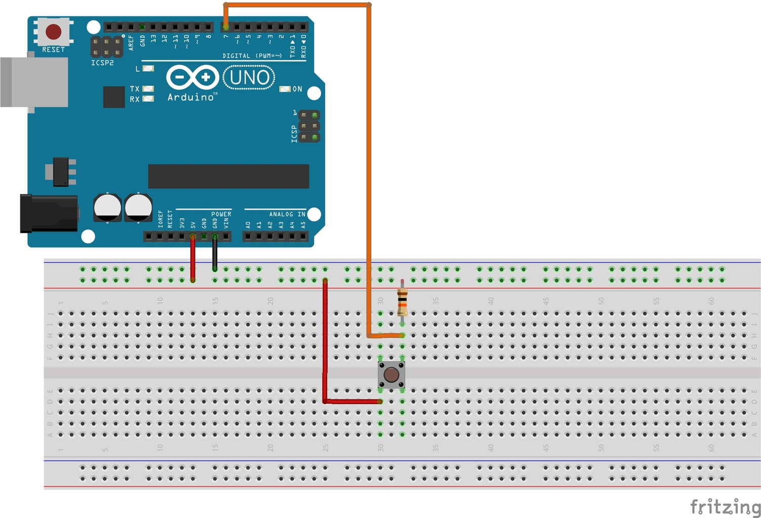
In order to trigger the indicator LED on the Slave Arduino, we need a trigger device. In this case, we will be using a pushbutton. The button has 4 pins, with two on each side. The pins of the button are interconnected diagonally in pairs. Since the bridge of the breadboard disconnects the two sets of columns, placing the button with two pins on either side of the bridge will prevent the circuit from shorting. Provide power to the button by connecting one of its ends to the Arduino 5V VCC and the diagonally opposite end to GND via a 10k ohm resistor. At the junction of the button and the resistor to GND, connect another wire to digital pin 7 on the Arduino for data input.
To program the button to send data via bluetooth, begin by defining the button pin as 7 and setting a variable to read the button's state.
#define buttonPin 7
int state = 0;
In the setup section, define the button pin as an input device and start Serial communication at a rate of 9600 baud.
void setup () {
	pinMode(buttonPin, INPUT);
	Serial.begin(9600);
}
In the loop section, begin by reading the button's state, then writing this data to the serial connection if it is available. Be sure to include a print statement for debugging, too (you can use the Serial monitor to check what data is being sent).
void loop () {
	state = digitalRead(buttonPin);
	if (Serial.available() > 0) {
		Serial.write(state);
		Serial.println(state);
	}
}
Upload this code to the Arduino after disconnecting the Master HC-05's RX/TX pins.
Attachments
Step 8: Connecting the Arduinos and Testing

To test the bluetooth connection, start by disconnecting the Slave device from any others (such as your Android), and then setting up the Master HC-05 in "normal" transceiver mode. To debug, it may be wise to keep the Slave Arduino connected to your PC, with the Serial monitor running. Power up the Master Arduino using a 9V battery and Arduino DC jack connector, placing it a distance away from the Slave. The two devices should connect automatically, which can be indicated by the onboard LED, which should blink twice every 2 seconds.
To test the device, press the push button. The LED should turn on as long as you hold the button down.
Congratulations! You have successfully tested the HC-05 and completed the first step in the Camera Surveillance Project.

![Tim's Mechanical Spider Leg [LU9685-20CU]](https://content.instructables.com/FFB/5R4I/LVKZ6G6R/FFB5R4ILVKZ6G6R.png?auto=webp&crop=1.2%3A1&frame=1&width=306)


