

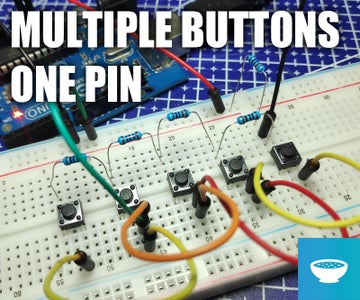
Introduction: Connecting Multiple Buttons to a Single Pin on Arduino


Hi Everyone,
When your Arduino projects have outgrown blinking LEDs, you may find yourself in a need of some extra pins.
I’ll show you a trick that you can use where you can have multiple buttons, all connected to the same analog pin.
Step 1: Materials
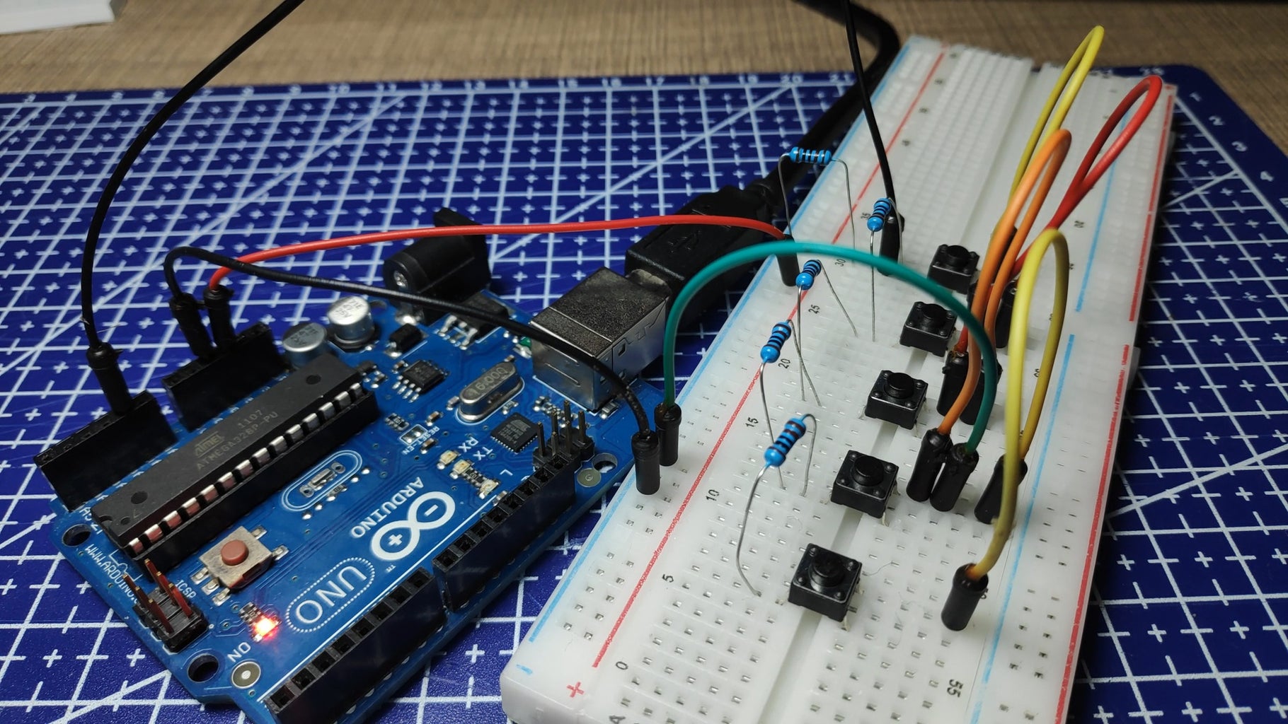
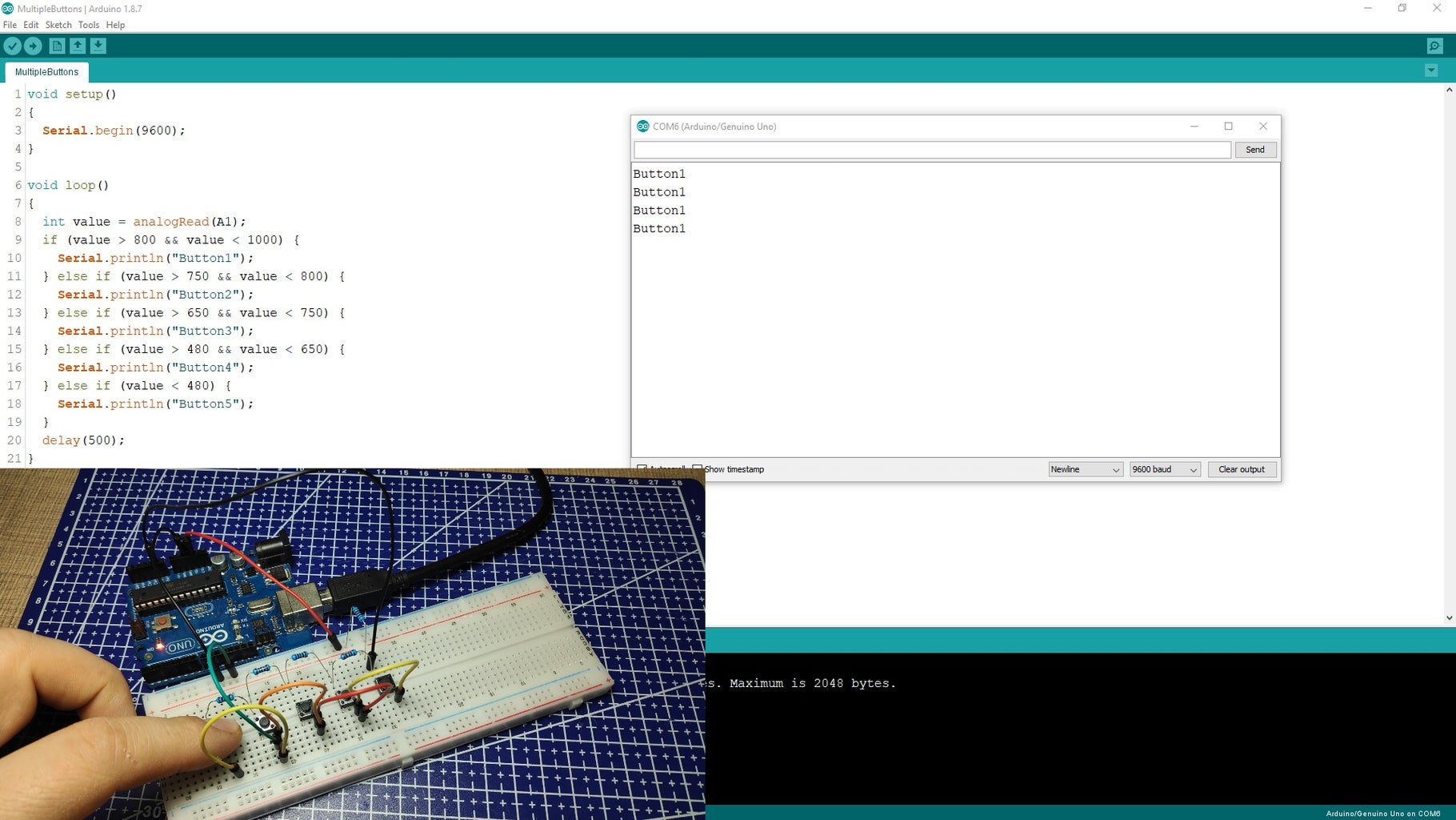
The circuit is very simple and it just requires a 1kOhm resistor for every switch. Basically, we are building a voltage divider where by the press of each of the buttons we connect different number of resistor to the analog input on the Arduino.
Step 2: Schematic
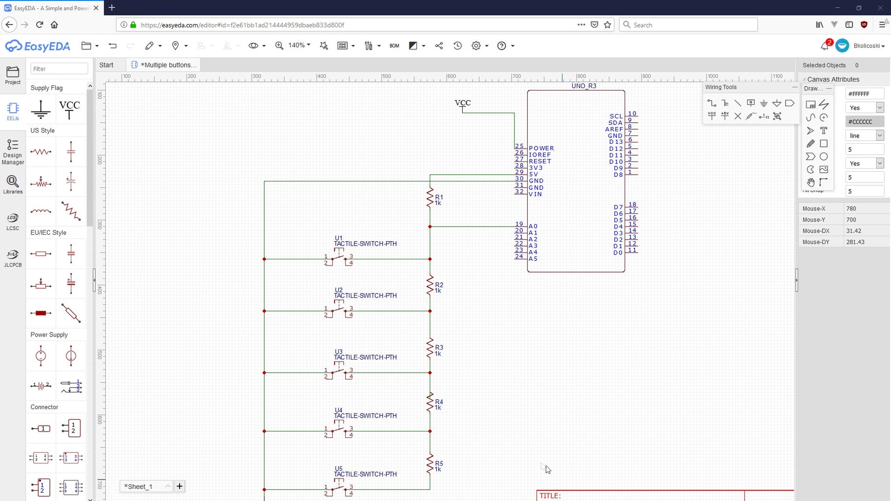
Start by connecting one of the resistors to the 5V output and one side of the first switch. The other side of the switch needs to then be connected to ground. Every additional button will be connected with its own resistor in series with the first one and ground on the other side.
The analog input pin is connected in between the first resistor and the first input button.
The full schematic in EasyEda is available here:
https://easyeda.com/bkolicoski/Multiple-buttons-on...
Step 3: Code

The code is very simple where in the first line of the loop function we read the value of the analog input and then we compare it with a certain threshold to determine which button is being pressed. To identify the right values I first had only the value from the analog pin printed to the serial monitor and then I’ve converted it to the right range.
Full code can be downloaded from my GitHub page:
https://github.com/bkolicoski/arduino-one-pin-butt...
Step 4: Further Expansion

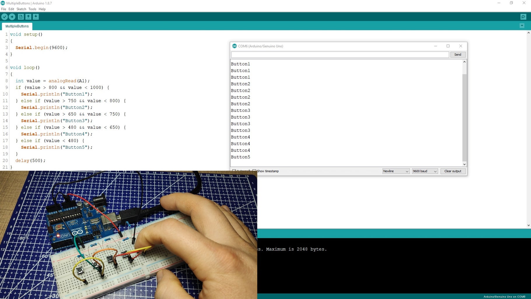
This method can be easily scaled to a lot of buttons but keep in mind that the more you add the smaller the threshold difference will be so any variations in the input voltage might cause a wrong reading. However, for regular operations for up to 10~15 buttons, this should not be an issue.


