

Introduction: Control Scanner Light With Arduino


Hello!
If you have broken or old scanner at home. This is a very cool project to play with. Every scanner has a light that moves when scanning is running. The best thing is that that light can be red, green, blue, or mixed.
With Arduino you can easily change colours on the way you want.
But we need to be careful, these lights can take lots of current and harm your Arduino board.
Please also check my video about this project to see what we will be making .
https://www.youtube.com/watch?v=9sakFor4EH4
For this project we will need:
-scanner light
-Arduino
-three transistors (i used 2222)
-three resistors (330 ohm)
-battery (3,7 or 9 V)
-breadboard
-wires
Step 1: Prepare Scanner Light


First, we need to find a broken or old scanner. Then we need to extract light from it.
Connector cable of your scanner can have lot's of wires. We need only four wires, but you need to identify it. I used a small 4 V battery to find which wires I need.
With 4 v batteries I was able to find out that first wire on the cable is common + voltage second wire= ground for blue third wire =gnd for green forth wire= grounds for red.
I soldered wires to connect the cable.
I also secured it with tape. Now is much easier to connect scanner light.
Step 2: Check Your Light

Now we need to test our light, you will need a battery and multimeter if you have one.I connected light directly to 4V battery to find out how much current it needs.Green and blue colours need around 80 am, Red colour needs more than 200 MA.
That current is too high for Arduino, so we can't connect light directly to Arduino.
Check my video to get more informations: https://www.youtube.com/watch?v=9sakFor4EH4
Step 3: Conecting Light to Arduino.


We will need three transistors for this. A transistor is used as switch in this example.
Remember! Current is too big, so we cannot connect scanner light directly to the Arduino board.
We need to use transistors, relays or some others switches. For this you will also need two resistors 330 ohm, you can use even higher values.
You can download schematic here:
https://drive.google.com/open?id=0BzYhjTpbP20DZVE3...
If you have problems with connectig check this video:
https://www.youtube.com/watch?v=9sakFor4EH4&feature=youtu.be
Step 4: Upload Code to Your Arduino
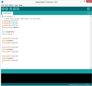
The code is very simple for this. This is just simple example how to change colors.You can modify the code later. You can even mix colours to get new colours.Speed of changing colors is controlled by delay () command. I hope that you will have fun and that this tutorial will be useful to you! Have a nice day!
Code:
void setup() {
pinMode(2,OUTPUT);
pinMode(3,OUTPUT);
pinMode(4,OUTPUT);
}
int timeee=500;
void loop()
{
digitalWrite(2,1);
delay(timeee);
digitalWrite(2,0);
digitalWrite(3,1);
delay(timeee);
digitalWrite(3,0);
digitalWrite(4,1);
delay(timee);
digitalWrite(4,0);
}

Participated in the
Arduino Contest 2016


