

Introduction: DAGU ROVER WITH DRONE


We are students from Irvington High School. In the past few months, we have worked on a project that develops an autonomous dagu rover 5 that transports a portable charger for a drone. To create our project, we programmed the dagu rover 5 using the moto 4 board. After that, we created a 3-D printed platform for our drone to land on through using Autodesk Inventor Software to generate a stl. File. The last part was creating a 3-D printed chassis for a drone motor board that we salvaged from a dead Husban drone. This project can be divided into 3 Main steps. Follow these steps, and you can have fun creating a drone with a landing pad.
1. Calibrate and write the code for the Dagu 5 Rover to be Autonomous.Use Autodesk Inventor to create the stl. Files necessary to create a 3-D printed charging dock for the drone.
2. Calibrate and assemble the Husban Drone with motors and flight controller.
3. 3-D print a chassis for the drone.
Step 1: Coding the Dagu Rover 5


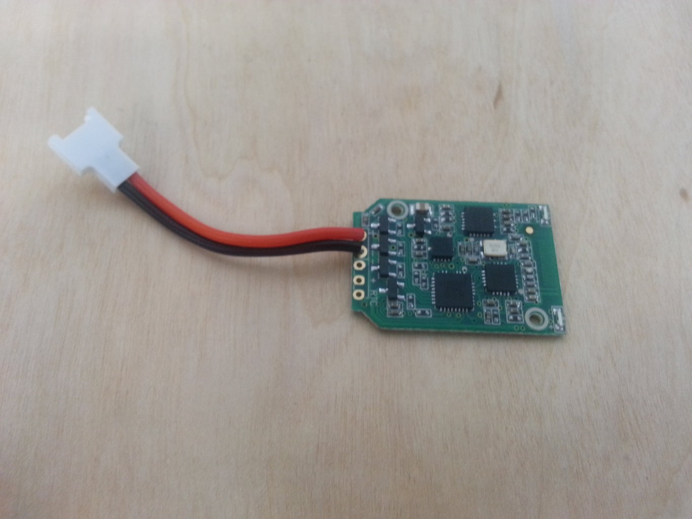
In this step, you need the Dagu Rover 5, or any other rover like chassis to continue. Where I got my Dagu Rover 5 was on.http://www.kr4.us/rover-5-robot-platform.html?gcli However, you do not necessarily need the one with encoders. You could also use of the other rover chassis that you have at your disposal. To calibrate the rover, we used an arduino and the moto 4 board. You can easily find a sample code online, but you should definitely write your own code as a learning experience and a way for you to program your autonomous rover to your own purposes.
For the arduino, the wiring format for the arduino and the motor board and the rover is shown in this picture files above.
Step 2: Calibrating the Internals of the Husban Custom Drone


The internals of the Quadcopter are pretty easy to solder and assemble if you are buying the parts from the internet. Amazon itself, has every single component you need. Here is the list.
I recommend buying an extra set of motors from the crash pack, but you do not need to purchase these if you are a pretty skilled pilot. (Buy it on amazon's husban crash kit.)
1x Radio transmitter: Hubsan H107C-19 4-Channel 2.4GHz [$24]
1x Radio receiver+flight control: Hubsan H107-A34 [$19]
4x Motors: Hubsan 7x20mm (2x CW, 2x CCW) for H107L [$7]
4x LED: Hubsan H107L & H107C LED (2x Red, 2x Blue, 3mm diameter) [$6
]4x Propellers: Hubsan H107-A02-PRO (2x TypeA, 2x TypeB) [$2]
1x Battery: HUBSAN HS-H107-A24 3.7V 380mAh Li-Po Battery [$9]
1x Charger: Hubsan 3.7V Usb Charger [$2]
2x screws: Hubsan Part H107-A07 Screw set [$2]
The grand total gets you at around 50 dollars, which is decent i guess.
Once you get these parts, follow Super Joohanson's steps https://www.instructables.com/id/Super-Light-Quadco...
Step 3: 3D Printing the Drone Chassis


What my partner and I did was we salvaged a toy Husban drone. After we took apart its internals, we went online and did some research on custom cases for the components. Since our case broke, we borrowed a design from Super Joohanson, who made a super awesome case and battery clip that is 3D printed. You can access his files here: https://www.instructables.com/id/Super-Light-Quadc
Furthermore, you can make your own case, but make sure to only set the case at one shell and 10 percent infill or else the drone will be too heavy for four 65 mm motors to fly.
The settings for the print that you should put on your 3D printer is that it needs a 10 percent infill and 1 shell. The other settings are shown in the images above.
Step 4: Printing the Rovers Body and Landingpad
We ran into some problems while printing out both the body and the landing pad, they continued to bend upwards , we finally fixed this by re-leveling the print platform. One other problem was that after printing the body, re realized that it didn't fit, but after a little bit of sanding down it fit perfectly. Be sure to use a low infill for both the body and the landing pad or it will increase the print time and be a huge waste of filament, I would say use a 10-15% infill. Once you have them both printed out we used hinges on the side to attach them too each other. Then you can also cut out a piece of acrylic to put into the slot in the front of the body. The slot itself is 3.25 by 3.53 by 0.24. so the piece you cut should be around 3.19 by 3.45 by 0.2.


