

Introduction: DIY 5.1 Home Theater System 700watt RMS


Make you own high quality 5.1 Home Theater System which is 700 watts RMS. 5+1 channel. 5 channels are 100 watts each and subwoofer is 200 watts ((5*100w)+(1*200w)=700w) (Front- left, Front- right, Center, Surround- left, Surround- right, Subwoofer). It is remote controlled. It has 4 - L/R inputs(Stereo) and one 6 channel input. Among four inputs one is for USB/MP3 player with built in Bluetooth. It also has SD card slot, USB slot, Aux input and listen songs from your mobile through Bluetooth. I am not able to find any suitable cabinet for this amplifier. I purchased locally available metal box and I cut and installed all the components as per requirement.
Enjoy making it.
Step 1: Requirements


- 5.1 remote control kit
- Cabinet
- 22-0-22 or 24-0-24 5 amps Transformer
- 12-0-12 1 amp Transformer
- 0-12 500ma Transformer
- Mains cord
- USB/MP3 player with built in bluetooth
- Large Heatsink's
- Cooling fans
- ON/OFF rocker switch
- 4 Way Spring Loaded Terminal Connector
PCB plastic spacers
RCA female connectors
- 1*10" subwoofer
- 2*3" tweeters
- 2*4" subwoofers
- 6*4" Mid speakers
For electronics components please view the circuit diagrams.
Step 2: 5 Channel PCB


I designed PCB in Diptrace. File attached.

Step 3: Subwoofer


I have two circuits. One is with TDA 7294 and another is TIP 142 and TIP 147 Transistors. Both work very well. I preferred TDA IC because all the remaining channels are with TDA and distortion will be less. In this two Ic's are combined as a bridge. I provided transistor circuit and also PCB. Use bigger heatsink and cooling fan for TDA circuit.
Differences --------------- TDA 7294 ----------------- Transistor Circuit
Quality ------------------------Good ---------------------Better than TDA 7294
Voltage range --------------(+/-35 v) ----------------------(+/-54 v) (Checked)
Heat dissipation -------------More --------------------------Very less
Distortion-------------------Very less----------------------------less
Step 4: Alternate Amplifier Board


If you are new in making PCB's , better to buy assembled boards. Visit the link : TPA 3116 Amplifier Board .
It is a class D amplifier with two channels and 50w each. In order to make 6 channels we need three boards. Total 300w RMS. Voltage range is 12-24v DC Single power supply. For separate 100w subwoofer amplifier please visit TPA 3116 subwoofer 100w . The sound quality is good and these boards are very cheap. In order to work with these boards we have to remove the volume controls that are soldered to the PCB.
Step 5: Power Supply

Here I used 3 transformers. One is 22-0-22 5 amps which gives +/- 35 v DC. I used 4 10000MFD 63v capacitors. This is for the amplifier. It is better to use 10 amps transformer if you want to utilize full power. Another is 12-0-12 1 amp for remote control kit. and 0-12v 500ma for cooling fans. I used two cooling fans. Designed PCB attached. Please open in Diptrace software.
Attachments
Step 6: Remote Control


I purchased this remote kit from this site.
http://imranicsworld.blogspot.in/2014/
The sound quality is amazing. The subwoofer filter does not sound good, so I found another best circuit from Internet. I have provided the PCB in next step. After replacing the subwoofer filter it sounded amazing. We have to power this kit with separate 12-0-12, 1 amp Transformer. For remaining details please visit the website.
System Features:
- External usb board control fuction is also provided for usb control.
- It has a rotary ENCODER which is also used to control all its function adjustments.
- This kit gives u a true pro-logic effect on rear channels with a best quality of sound.
- Digital gain option is provided for individual channel corrections and input gain correction.
- Each input gain and individual output channels gain can be adjusted using remote control.
- Memory function is provided for audio levels and also audio inputs.
- Low pass filter circuit is provided as a separate unit for user adjustments and can be modified.
- Soft mute fuction is used for audio mute.
- 2 band tone control (BASS/TREBLE).
- Display software is modified to give a bigger size numbers for audio level for user visibility.
OUTPUT PORTS FOR EXTERNAL HARDWARE CONTROL:
- 4 output lines for external usb board (CHINA USB BOARD ) control for its basic operations such asPLAY /PAUSE , MODE (usb/fm), TRACK PERV << and >> TRACK NEXT.
- 1 MUTE signal line out.
- 1 STAND-BY signal line out.
- 1 USB +5V output signal.
ROTARY ENCODER FUNCTIONS:
- Volume up/dwn for master control and front ,rear, centre ,subwoofer volume adjustments.
- Bass/Treble adjustments.
- Input selection.
AUDIO PROCESSOR FEATURES:
- 6 channels independent electronic volume (0 to –99dB/1dBstep, –∞dB)
- 6 channels independent gain control (0 to +14dB/ 2dB step)
- L/R channel 4 input selector (Input gain: 0 to +14dB/ 2dB step)
- Multi channel input: 6 channels input
- Tone control Bass: –14 to + 14dB(2dB step),Treble: –14 to + 14dB(2dB step)
- Can use 1 input for REC output (REC output gain: 0, +2, +4, +6dB)
- Built-in ADC output (Input Att: 0/ –6/ –12/ –18dB)
- Built-in L+R/ L–R block
- Built-in digital power supply
These features and functions are taken from the website.
Step 7: Subwoofer Filter


This subwoofer filter is based on NE5532 IC. I modified the circuit by replacing 47k presets with 1ohm resistors. The sound quality is amazing. I attached the circuit and PCB layout.

Step 8: USB/Mp3 Player


Better use USB/MP3 with built in bluetooth module. If not use an external bluetooth receiver.
Step 9: Wiring


Connect according to the block diagram.
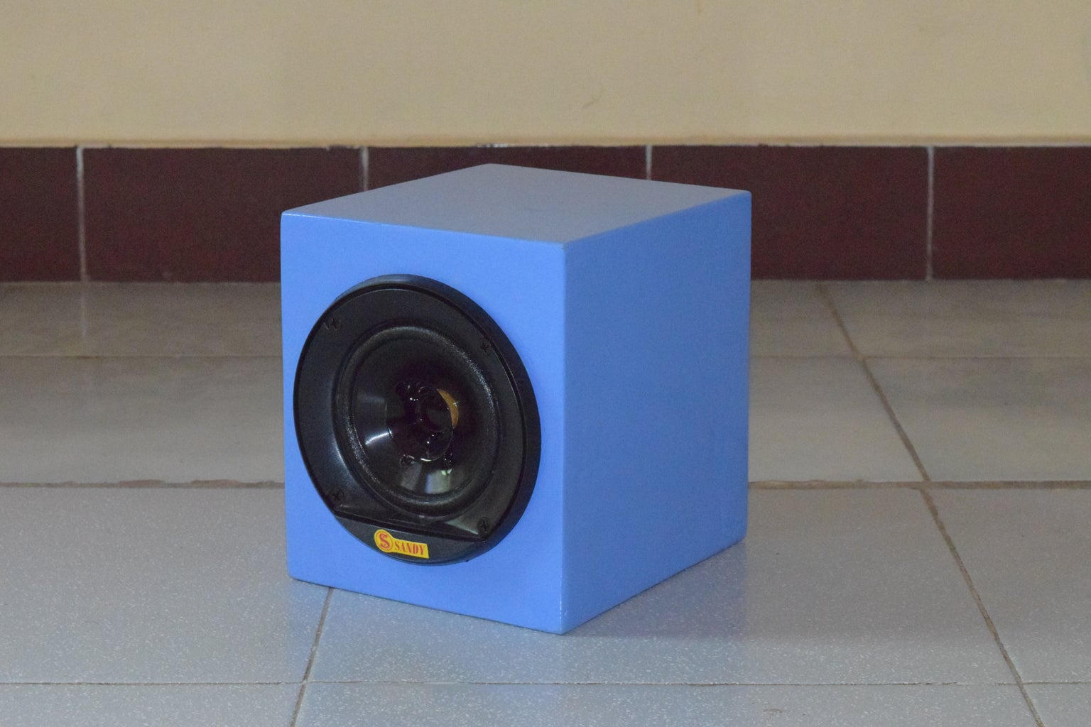
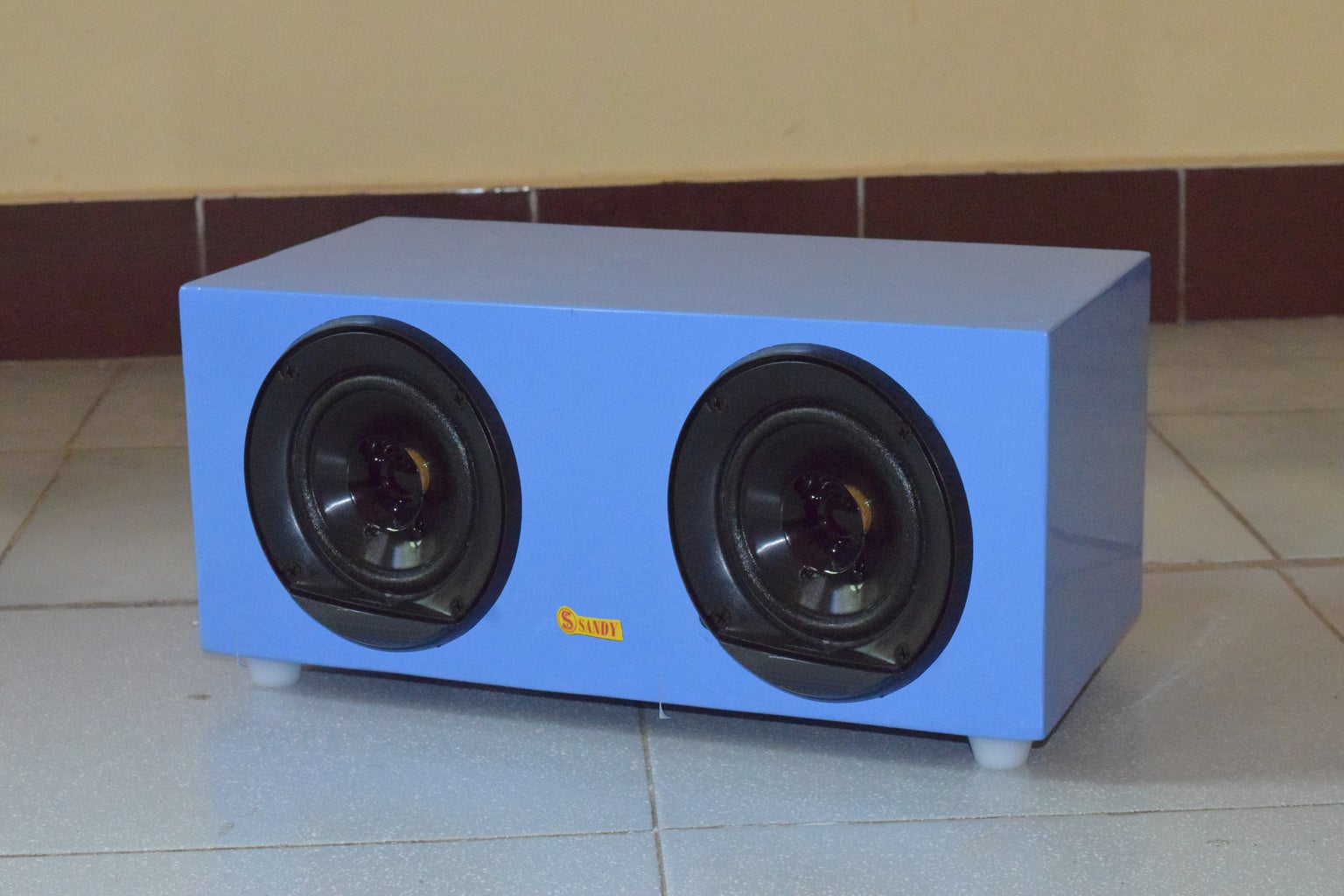
Step 10: Speaker Enclosures


I have made these enclosures with 12mm MDF. Measurements given in pictures. Subwoofer enclosure is old one.
Step 11: Paint Job

Applied primer and painted with blue color. Installed all the speakers.
Step 12: Final Step


Label the cabinet.
Enjoy the music...

Participated in the
Audio Contest 2017

Participated in the
Wireless Contest


