

Introduction: DIY IRONLESS LINEAR SERVO-MOTOR


Hi,
in this Instructable I want to show you, how to build your own Linear-Servo-Motor for Linear-Movement-Applications.
But at first the story about this Instructable:
When I visited one of the biggest trade faires for Automation here in Germany, I saw a lot of Linear-Motors in Industry Applications. It was quite astonishing how fast these Motors can move with an incredible precision.
I thought it would be really cool, if I could addapt these kind of motor in a Laser or 3D-Printer Application. Sadly these Motors are very expensive (>1000€ per piece). So buying a Linear-Motor is not an option anymore. But after some research I thought it will be possible to build my own Linear-Motor. Theoretecly a Linear-Servo-Motor is just a three phase sychronous motor with a closed loop position feedback. So I started to create CAD-Drawings and Electronics. After one month of research and improvements I can say, I have built my own working Ironless Linear-Servo-Motor. However there are some points which need to be improved especially in the position regulation. This project helped me a lot to understand, how a Linear-Motor works in general, and how to programm a closed-loop controller for it.

Specification:
Travel-Distance: 290mm
max. Travel-Speed: 200mm/s (at 24V, I think there is much more possible, but my coils are getting to hot above 24V)
accuracy: 0.3mm (remember there is just a 400pulse/rev encoder)
cost: <100€ if you have all the tools like CNC-Mill and 3D-Printer at home.
Videos:
Fast movements; position is set in the Arduino-File:
Fixed position; the Motor tries to withstand external forces to keep his position:
### If you like my Instructable, please vote for me in the Epilog-Contest 10###
### You can see this motor live at Maker Faire Ruhr 2019 ###
Step 1: The Theory of the Linear Motor
Theoretectly a Linear Motor is just an unrolled three phase Motor. You controll the Linear-Motor like a rotary motor by connecting a three phase sinusiodle current at each of the coils. The coils will create a periodic moving magnetic field, which will result in a force which will drive the motor. For a better imagination, please take a look at this Wikipedia article. Sadly the infomations, which are necessary to build an Ironless Linear Motor aren't descriped that well in this article, so I have written down my own experiences, while building this motor. At frist it sounds simple "just three coils between some magnets", but after some tests, I could say it was really hard to find the right parameters:
The arrangement of the coils to the magnets:

The coils needs to be arranged to the magnets like seen above, this kind of arrangement will cerate the optimal force to the three coils . Because I have choosen to build an ironless type linear motor, that means that there is no iron or any other material with a high permability inside the coils, there are a few points you need to consider about, before start building your own motor:
- The distance between the lower and upper magnets:

One of the main problems of a motor is the gab of air between the coils and magnets . On the one hand the magnetic field between the magnets will be increased, by decreasing the distance between them. On the other hand, there are still the coils between the magnets, which needs to be fixed in there position and also need to withstand the applied current. After some experiments with different kinds of coil fixtures and distances, I found out that the best distance between the magnets is 6mm (This is not the mathematical perfect distance, but for me it is the closest distance I could reach if you consider that I need to create the fixture and the coils by myself).
- The Iron back circuit:


As said above the resistance of the magnetic flux will be increased by low permability materials like air. But if you will use a high permability material like Iron, the resistance for the magnetic flux will drop significantly. The conclusion is to use some iron sheets from the outside to mount the magnets. Just because of two sheets of iron, the magnetic flux between the two magnets will be increased.
- The coils:
The installed coils have a dimension of 16x26mm and are made out of 0.2mm copper isolated wire. The coils are just 3mm thick. You will find more information about the coils in step 5.
Step 2: Mechanical-Parts


The complete motor is designed with Fusion 360. Below you will find all requiered parts and files of the motor:
Fusion 360 File:
Standart-Parts:
| Quantity | Description | Link | Price |
|---|---|---|---|
| 1x | 20x40x400mm aluminium extrusion | Dold-Mechatronik | 3,50€ |
| 1x | 350mm MGN9 Linear rail with MGN9H Wagon | Aliexpress | 12,88€ |
| 1x | 2m GT2 Belt 6mm width | Aliexpress | 0,72€ |
| 56x | 10x20x3mm N35 neodym magnets | Aliexpress | 19,01€ |
| 6x | F623ZZ flanged ball bearings | Aliexpress | 2,51€ |
| 1x | GT2 Pulley 20 Teeth 6mm Bore | Aliexpress | 2,79€ |
Nuts, Screws and Washers:
| Quantity | Description | Where to buy | Price |
|---|---|---|---|
| 4x | M5x20mm DIN912 cylinderhead screw | local hardware store | - |
| 2x | M5x10mm DIN912 cylinderhead screw | local hardware store | - |
| 6x | M4x20mm DIN912 cylinderhead screw | local hardware store | - |
| 4x | M4x10mm DIN912 cylinderhead screw | local hardware store | - |
| 2x | M3x30mm DIN912 cylinderhead screw | local hardware store | - |
| 2x | M3x25mm DIN912 cylinderhead screw | local hardware store | - |
| 10x | M3x16mm DIN912 cylindergead screw | local hardware store | - |
| 30x | M3x8mm DIN912 cylinderhead screw | local hardware store | - |
| 5x | M5 T-Slot-Nut | 5,33€ | |
| 4x | M4 T-Slot-Nut | 5,33€ | |
| 18x | M3 T-Slot-Nut | 5,33€ | |
| 4x | M3 Nut | local hardware store | - |
| 4x | M5 washer | local hardware store | - |
| 10x | M4 washer | local hardware store | - |
| 25x | M3 washer | local hardware store | - |
CNC-Milled-Parts:
All installed aluminium parts are milled on my diy CNC-Router. The most complex part to machine is the carriage fixture, because this part requiered a two side machining. The steel parts for the forcer are handmade, because my CNC machine has not the capability to mill steel. You can download all the CAD-Files at the bottom of this step.
| Quantity | Description | How the part looks like |
|---|---|---|
| 1x | Carriage |  |
| 1x | forcer |  |
| 1x | Carriage_top_1 |  |
| 1x | carriage_top_2 |  |
| 1x | encoder_plate |  |
| 1x | spacer |  |
| 2x | foot |  |
| 1x | pcb_plate |  |
| 1x | steel_plate_top | 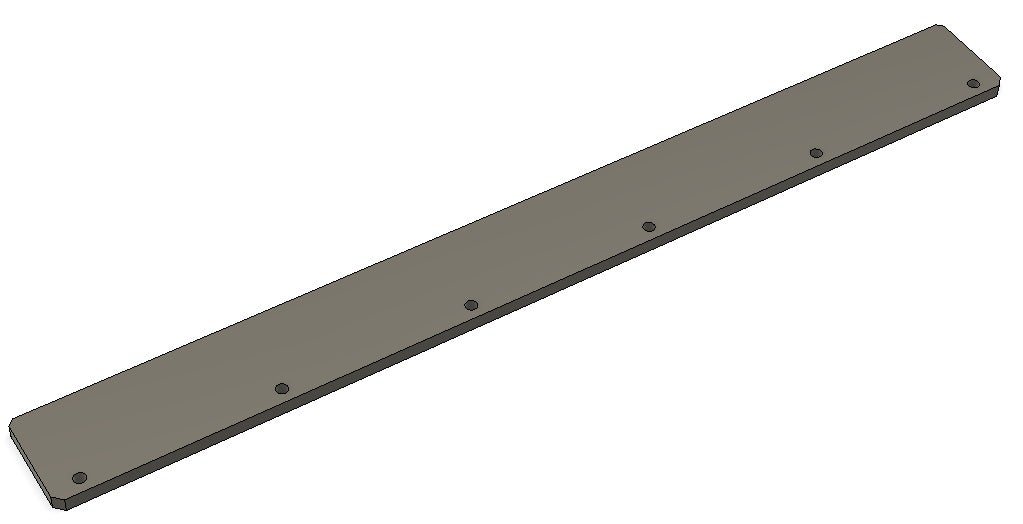 |
| 1x | steel_plate_bottom |  |
3D-Printed Parts:
The 3D-Printed parts are made out of PLA with a resolution of 0.1mm. All requiered .stl files are aviable at the bottom of this step. If you don't have a 3D-Printer, you can buy the 3D-Printed-Parts here.
| Quantity | Description | How the part looks like |
|---|---|---|
| 1x | forcer_top.stl |  |
| 1x | forcer_bottom.stl |  |
| 1x | encoder_spacer.stl | 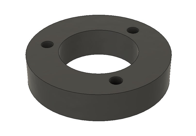 |
| 2x | bumper.stl |  |
| 4x | pcb_spacer.stl |  |
| 4x | pcb_foot.stl |  |

Step 3: Electrical-Parts
Electronic Parts for the Motor:
| Quantity | Description | Link | Price |
|---|---|---|---|
| 1x | Rotary Encoder 400pulse/rev | Aliexpress | 11,41€ |
| 3x | 100m 0,2mm copperwire | Aliexpress | 6,62€ |
| 3x | 1m Wires 22AWG (black , red , yellow ) | Aliexpress | 3,30€ |
| 9x | terminals | local hardware store | 0,20€ |
Electronic Parts for the PCB:
Here are all required parts for the Linear Motor. I tried to source all parts as cheap as possible.
| Quantity | Description | Name on PCB | Link | Price |
|---|---|---|---|---|
| 1x | Arduino Nano | U1 | Aliexpress | 1,77€ |
| 1x | L6234 Three phase H-Bridge | U2 | Aliexpress | 3,00€ |
| 8x | 1k Resistor | R1-R8 | Aliexpress | 0,53€ |
| 1x | Pinheader | JP1-JP4 | Aliexpress | 0,48€ |
| 1x | 2-Pin screw-terminal | J1 | Aliexpress | 0,82€ |
| 1x | 3-Pin scew-terminal | J2 | Aliexpress | 1,25€ |
| 1x | 7805 Linear Voltage Regulator | IC1 | Aliexpress | 0,86€ |
| 2x | 1N4148 Diode | D1, D2 | Aliexpress | 0,82€ |
| 2x | 0.1µF capacitor | C1, C7 | Aliexpress | 1,20€ |
| 1x | 0.33µF capacitor | C6 | Aliexpress | 1,20€ |
| 1x | 10nF capacitor | C3 | Aliexpress | 1,20€ |
| 1x | 220nF capacitor | C2 | Aliexpress | 1,25€ |
| 1x | 100µF polarized capacitor | C4 | Aliexpress | 1,24€ |
| 1x | 1µF polarized capacitor | C5 | Aliexpress | 0,62€ |
Here are all the files for the requierd PCB. I have attached all files for manufacturing: gerber files , eagle cad files and even etch templates, if you want to create your PCB with the toner transfer methode. I have created the PCB by a professionell manufacture. The PCB is just single side, so it will be easy to make.
| Quantity | Description | Top View | Bottom View |
|---|---|---|---|
| 1x | PCB |  |  |

Step 4: Building the Motor: the Magnetic Rail

What you need for this step:
| Quantity | Description |
|---|---|
| 48x | 10x20x3mm N35 neodym magnets |
| 6x | M4x20mm DIN912 cylinderhead screw |
| 6x | M4-washer |
| 1x | "spacer" aluminium part |
| 1x | steel_plate_top (in my case painted black) |
| 1x | steel_plate_bottom (in my case painted black) |
| 1x | 20x40x400mm aluminium extrusion |
What you have to do:
At frist you have to take the upper steel plate and place 24 magnets with alternating polarity on it. For the right distance of 3,33mm between the magnets I've created an allignment tool (See picture [2] below). Once all the magnets are in the right position, you have to fix them at their place with some super glue. Now repeat this procedure with the bottom steel plate.

Now you have to combine the upper and the lower steel-plate by using the six M4 Screws. You do that by using the "spacer" aluminium part. Because the magnets are so strong, I recommend to use a piece of wood or something similar to protect the magnets while assembling the steelplates.

Step 5: The Coils

What you need for this step:
| Quantity | Description |
|---|---|
| 3x | 100m x 0.2mm diameter isolated copper wire |
| 1x | "forcer" aluminium part |
| 6x | M4-washer |
| some | kapton tape |
| 1x | selfmade coil tool |
This is one of the most complicatest steps of the motor. I've personally needed around ten iterations, after I have found the right dimesion of the spools, which actually worked. You have to find the right parameters between current tollerance and diameter of the coil. If these two values fit together you will have a good coil.
Because there is no ferro-magnetic material in the "forcer", it will not amplifiy the magnetic field, so the field out of the coils needs to be strong enough to move the motor.
Specifications of my coils:
- 0.2mm copper wire
- 15 [Ohm] resistance
- +-100m of wire
Now I will show you how I have made the coils:
What you have to do:
At first you should print out my tool to wind the coils. It will simplify the process of the spool winding. So at first take the winding tool and attach some baking paper on both sides of the tool. This will be usefull in the next steps.


After that I am using a drilling machine to wind the wires on the tool. The wires need to fill the complete space between the two plates. Once finished, you can use some super glue to keep the wires in position and because of the backing paper, the glue will not stick to the fixture ;).


Once the glue is dried, you can remove the fixture carefully. The 3D-printed inlay of the coil is not going to be removed, it will stay there for ever.


You need to repeat this step three times. Finally you have to take the "forcer" aluminium part and place the three coils inside the three pre-milled pockets. To hold the coils in place I have used some kapton tape. The Advantage of kapton tape is, that it is very thin but also heat resistant, which is ideal for this application.


Attachments
Step 6: The Carriage

What you need for this step:
| Quantity | Description |
|---|---|
| 1x | assembled coil module |
| 1x | "Carriage" aluminium part |
| 1x | "Carriage_top_1" aluminium part |
| 1x | "Carriage_top_2" aluminium part |
| 1x | cable-chain |
| 1x | forcer_top.stl |
| 1x | forcer_bottom.stl |
| 6x | M3x8mm DIN912 screws |
| 4x | M3x30mm DIN912 screws |
What you have to do:
At frist you have to attach the coil module to the "carriage" alumnium part. You do that by using two M3x8mm screws.


After that you have to connect the coils to the wires. The coils need to be connected in triangle configuration. The connection is simply made by a terminal connector. 

Then it is time to close the connection box. For that you have to use the "forcer_top.stl" file.

Finally attach the cable chain to the upper aluminium plate.

Step 7: The Encoder Plate

What you need for this step:
| Quantity | Description |
|---|---|
| 1x | "encoder_plate" aluminium part |
| 1x | "encoder_spacer.stl" 3D-printed part |
| 6x | F623ZZ flanged ball bearings |
| 1x | GT2 Pulley 20 Teeth 6mm Bore |
| 3x | M3x16mm DIN912 cylinderhead screw |
| 3x | M3x16mm DIN912 cylinderhead screw |
| 6x | M3 washer |
| 1x | Rotary Encoder 400pulse/rev |
What you have to do:
At first you have to slide the GT2 Pulley on the encoder. Then you need to fix the Pulley by using the allen screws inside the pulley.

Now take the encoder and connect it to the "encoder_plate". Do that by using the three M3x16mm screws and the encoder_spacer.

In the following steps the bearings for the timing belt are going to be attached to the "encoder_plate":

Now put the bearings, screws and washers together. Repeat this three times:

Finally connect the bearings to the encoder plate:

Step 8: Bringing All Parts Together

What you need for this step:
| Quantity | Description |
|---|---|
| 1x | assembled encoder plate |
| 1x | assembled magnetic rail |
| 1x | assembled carriage |
| 1x | 350mm MGN9 Linear rail with MGN9H Wagon |
| 1x | 2m GT2 Belt 6mm width |
| 2x | "foot" aluminium part |
| 18x | M3x8mm DIN912 cylinderhead screw |
| 18x | M3 T-Slot-Nut |
| 4x | M4x10mm DIN912 cylinderhead screw |
| 2x | M5x10mm DIN912 cylinderhead screw |
| 4x | M5x20mm DIN912 cylinderhead screw |
| 2x | M5 T-Slot-Nut |
| 2x | "bumper.stl" 3D-printed part |
What you have to do:
At first you have to put the linear rail at the front of the
"magnetic-rail" module. After that attach the two bumpers on both sides of the rail. The bumpers will prevent the wagon from falling out.

Now it is time to attach the "foot" aluminium parts to the "magnetic-rail" module. For the connection, I have cut four M5-threads inside the aluminium extrusions. The alumnium parts are connected by four M5x20mm screws.

For the next step you need to place the "encoder-plate" module on the "magnetic-rail" module. The connection is made by four M4x10mm screws.
Now you have to connect the "heart" of the motor, the carriage. For the connection to the linear rail, you have to use the four M3x8mm screws. The cable chain is connected by two M3x8mm screws. 

Finally the GT2 belt needs to be attached to the rotary encoder. And you are done! The mechanical part of the motor is compelted. Now it's time to step over in electronics and programming :-) .

Step 9: The PCB


The motor is mainly controlled by an Arduino Nano and the L6234 motor driver chip. As you can see in the schematic I have also break out some pins, so that there will be a connectivity for a step/dir interface (not implemented yet).
For the builing of the circuit I recommend to manufacture a PCB. You can do this by yourself with the toner transfer methode or you can order it with the gerber files by a professionell manufacture like I did. All the requierd files are available in the "Electrical-Parts" step.
Because I could only purchase ten PCBs at one time, I will sell some of these PCBs in my onlineshop for only 2€.
Attachments
Step 10: Programming the Arduino
While I was experimenting with the first prototype of the linear motor, I took some inspiration from this article: berryjam.eu, this guy uses the same L6234 chip like me and he successfully move a brushless motor slow and with precision. The problem with this kind of motor controll is, that there is no feedback where the rotor is located. But if you want to drive a brushless motor or Linear Motor the fast way, you need the information, where the rotor is located, to switch the coils just at the perfect position. In brushless ESC controllers this is often done by HAL-Sensors. But for Linear-Motors with a position feed-back this is not the best option, because you only know where the coils are, when they are in movement.Also the resolution of the position feed-back isn't really accurate.
So for my application, the linear motor, I have tried a different way: I installed a rotary encoder, which is connected to the linear motor slider by a belt. This is used to measure the position of the coils, but also to read out the actual position where the slider is located. While using this technic I have solved both problems, the perfect switching of the coils and also the knowledge, where the slider is actually located. So I wrote a small programm on the arduino which will excatly do this kind of motor controll.
The complete code:
 #include <PID_v1.h>

const int encoder0PinA = 2 ;
const int encoder0PinB = 3 ;

volatile int encoder0Pos = 0;

const int EN1 = 5;
const int EN2 = 6;
const int EN3 = 7;

const int IN1 = 9;
const int IN2 = 10;
const int IN3 = 11;

double Setpoint, Input, Output;
PID myPID(&Input, &Output, &Setpoint,2,5,1, DIRECT);

// SPWM (Sine Wave)
int pwmSin[72] = {127, 138, 149, 160, 170, 181, 191, 200, 209, 217, 224, 231, 237, 242, 246, 250, 252, 254, 254, 254, 252, 250, 246, 242, 237, 231, 224, 217, 209, 200, 191, 181, 170, 160, 149, 138, 127, 116, 105, 94, 84, 73, 64, 54, 45, 37, 30, 23, 17, 12, 8, 4, 2, 0, 0, 0, 2, 4, 8, 12, 17, 23, 30, 37, 45, 54, 64, 73, 84, 94, 105, 116 };

enum phase {PHASE1, PHASE2, PHASE3};
int count[] = {0,24,48};

int *pos_U = pwmSin;
int *pos_V = pwmSin + 24;
int *pos_W = pwmSin + 48;

const double abstand = 27; //24

int directionPin = 4;
int stepPin = 12;

double step_position = 0.0;

int test;

double position_in_mm = (encoder0Pos) / 40.00;


void setup() {
  pinMode(encoder0PinA, INPUT);
  pinMode(encoder0PinB, INPUT);

  // encoder pin on interrupt 0 (pin 2)
  attachInterrupt(0, doEncoderA, CHANGE);

  // encoder pin on interrupt 1 (pin 3)
  attachInterrupt(1, doEncoderB, CHANGE);

  step_position = 0;


  setPwmFrequency(IN1); // Increase PWM frequency to 32 kHz  (make unaudible)
  setPwmFrequency(IN2);
  setPwmFrequency(IN3);

  pinMode(IN1, OUTPUT);
  pinMode(IN2, OUTPUT);
  pinMode(IN3, OUTPUT);

  pinMode(EN1, OUTPUT);
  pinMode(EN2, OUTPUT);
  pinMode(EN3, OUTPUT);


  digitalWrite(EN1, HIGH);
  digitalWrite(EN2, HIGH);
  digitalWrite(EN3, HIGH);

  analogWrite(IN1,*pos_U);
  analogWrite(IN2,*pos_V);
  analogWrite(IN3,*pos_W);
  delay(2000);
  analogWrite(IN1,0);
  analogWrite(IN2,0);
  analogWrite(IN3,0);


  encoder0Pos = 0 ;
  Input = encoder0Pos / 40.00 ;
  Setpoint = step_position;
  myPID.SetOutputLimits(-1000, 1000);
  myPID.SetMode(AUTOMATIC);
  myPID.SetSampleTime(1);
  unsigned long previousMillis = 0;

}


unsigned long previousMillis = 0;
const long interval = 500;
int ledState = LOW;
int i = 0;


void loop() {

int positions[2] = { -100.0 , 0};

myPID.SetTunings(15,0,0.4); //val_1,0,val_


Input = encoder0Pos / 40.00;
myPID.Compute();
drive(Output/1000);
Setpoint = positions[i];
unsigned long currentMillis = millis();

  if (currentMillis - previousMillis >= interval) {
    previousMillis = currentMillis;
    if (i < 1) {
      i++;
    } else {
      i = 0;
    }
  }

}

double newmap(double x, double in_min, double in_max, double out_min, double out_max){

  return (x - in_min) * (out_max - out_min) / (in_max - in_min) + out_min;
}

void drive(double scale_factor){

if(scale_factor < 0.00){
double  temp = -scale_factor;
temp = (temp - 0.00) * (1.0 - 0.1) / (1.00 - 0.00) + 0.1;

test =- ( count[0] - berechne() + 24) ; // +24
  shift(&pos_U, test , 72, PHASE1);
  shift(&pos_V, test, 72, PHASE2);
  shift(&pos_W, test, 72, PHASE3);

  analogWrite(IN1,*pos_U * temp );
  analogWrite(IN2,*pos_V * temp );
  analogWrite(IN3,*pos_W * temp);
return;
}

if(scale_factor > 0.00){
test = (- count[0] + berechne() + 24) ;
scale_factor =(scale_factor - 0.00) * (1.0 - 0.1) / (1.00 - 0.00) + 0.1;
  shift(&pos_U, test , 72, PHASE1);
  shift(&pos_V, test, 72, PHASE2);
  shift(&pos_W, test, 72, PHASE3);

  analogWrite(IN1,*pos_U * scale_factor );
  analogWrite(IN2,*pos_V * scale_factor );
  analogWrite(IN3,*pos_W * scale_factor);

return;
}

if(scale_factor == 0.00)

return;

}

int berechne(){
 double position_in_mm = (encoder0Pos) / 40.00;
 int vielfaches = position_in_mm / abstand;
 double phaseshift2 = position_in_mm-(vielfaches*abstand);
 // Serial.println(phaseshift2);
double phaseshift3 = (phaseshift2 - 0) * (72 - 0) / (abstand - 0) + 0;
 //Serial.println(phaseshift3);
 return phaseshift3;

}

//######################## Shift-Array########################

void shift(int **pwm_sin , int shift_distance , int array_size, phase phase_number){
  if(shift_distance == array_size)
  return;

  if(shift_distance > 0){
  if(count[phase_number] + shift_distance < array_size){
  *pwm_sin = *pwm_sin + shift_distance;
   count[phase_number] += shift_distance ;
  }
  else
  {
    int temp =count[phase_number] + shift_distance - array_size;
    *pwm_sin = *pwm_sin - count[phase_number];
    *pwm_sin = *pwm_sin + temp;
    count[phase_number] = temp;

  }
  return;
  }


  if(shift_distance < 0){
    int temp_distance = array_size + shift_distance;
    shift(pwm_sin, temp_distance , array_size, phase_number);
  }


  if(shift_distance = 0 );
  return;
}


//########################### ENCODER-INTERRUPT#########################################
void doEncoderA() {
  // look for a low-to-high on channel A
  if (digitalRead(encoder0PinA) == HIGH) {

    // check channel B to see which way encoder is turning
    if (digitalRead(encoder0PinB) == LOW) {
      encoder0Pos = encoder0Pos + 1;         // CW
    }
    else {
      encoder0Pos = encoder0Pos - 1;         // CCW
    }
  }

  else   // must be a high-to-low edge on channel A
  {
    // check channel B to see which way encoder is turning
    if (digitalRead(encoder0PinB) == HIGH) {
      encoder0Pos = encoder0Pos + 1;          // CW
    }
    else {
      encoder0Pos = encoder0Pos - 1;          // CCW
    }
  }
  //Serial.println (encoder0Pos, DEC);
  // use for debugging - remember to comment out
}

void doEncoderB() {
  // look for a low-to-high on channel B
  if (digitalRead(encoder0PinB) == HIGH) {

    // check channel A to see which way encoder is turning
    if (digitalRead(encoder0PinA) == HIGH) {
      encoder0Pos = encoder0Pos + 1;         // CW
    }
    else {
      encoder0Pos = encoder0Pos - 1;         // CCW
    }
  }

  // Look for a high-to-low on channel B

  else {
    // check channel B to see which way encoder is turning
    if (digitalRead(encoder0PinA) == LOW) {
      encoder0Pos = encoder0Pos + 1;          // CW
    }
    else {
      encoder0Pos = encoder0Pos - 1;          // CCW
    }
  }
}

//#################### PWM-Motor#######################

void setPwmFrequency(int pin) {
  if(pin == 5 || pin == 6 || pin == 9 || pin == 10) {
    if(pin == 5 || pin == 6) {
      TCCR0B = TCCR0B & 0b11111000 | 0x01;
    } else {
      TCCR1B = TCCR1B & 0b11111000 | 0x01;
    }
  }
  else if(pin == 3 || pin == 11) {
    TCCR2B = TCCR2B & 0b11111000 | 0x01;
  }

}
Now I will explain you the main procedure of my arduino programm:
- The coils needs to be alligend to a predefined point, that the arduino knew, where the magnets are located. This is made by the putting a three phase voltage to the coils. So the slider will rast inside the magnetic field automaticly. After that the position of the motor is defined as zero. For further movements the position will be captured by an interrupt on Pin D2 and D3 now.
- The attached sinusiodal voltage needs to be sychronised with the magnet-positions. For that application, I have used the function berechne()
 int berechne(){
 double position_in_mm = (encoder0Pos) / 40.00;
 int vielfaches = position_in_mm / abstand;
 double phaseshift2 = position_in_mm-(vielfaches*abstand);
 double phaseshift3 = (phaseshift2 - 0) * (72 - 0) / (abstand - 0) + 0;
 return phaseshift3;
}
The function returns the right index of the pwm array, so that there is always the right field orientation between the coils and the magnets.
3.With this information I am able to drive the motor. This is done by the function drive() :
void drive(double scale_factor){
if(scale_factor < 0.00){
double  temp = -scale_factor;
temp = (temp - 0.00) * (1.0 - 0.1) / (1.00 - 0.00) + 0.1;

test =- ( count[0] - berechne() + 24) ; // +24
  shift(&pos_U, test , 72, PHASE1);
  shift(&pos_V, test, 72, PHASE2);
  shift(&pos_W, test, 72, PHASE3);

  analogWrite(IN1,*pos_U * temp );
  analogWrite(IN2,*pos_V * temp );
  analogWrite(IN3,*pos_W * temp);
return;
}

if(scale_factor > 0.00){
test = (- count[0] + berechne() + 24) ;
scale_factor =(scale_factor - 0.00) * (1.0 - 0.1) / (1.00 - 0.00) + 0.1;
  shift(&pos_U, test , 72, PHASE1);
  shift(&pos_V, test, 72, PHASE2);
  shift(&pos_W, test, 72, PHASE3);

  analogWrite(IN1,*pos_U * scale_factor );
  analogWrite(IN2,*pos_V * scale_factor );
  analogWrite(IN3,*pos_W * scale_factor);

return;
}

if(scale_factor == 0.00)

return;

}

}
This function recieves a double value which stands for the speed and the direction.The actual movement will be created by the function shift with the following analogWrite(). I simply shift the PWM-Array by a 1/3 periode, which causes a movement in the positiv direction. The speed of the motor is controlled by the scale_factor(). Which is the amplitude of the sinusiodal
4. Now there is only one last essential function: The PID controll loop. For that purpose I have used an allready finished PID-libary which can be loaded by the Arduino libary-manager. The PID-loop looks at the difference between the actual position and the desired position. The output will be a double value from -1.0 - 1.0 which can be used by the drive function.
I have to say this is not the best arduino code. Yes it works, but there are still some problems to solve especially the velocity and positioning regulation loop. I am also on the way to implement an interface with step and direction signals, but there are still some problems to solve like acceleration ramps and constant velocity. I am trying to update the software in the next time. So stay tuned for an update and please leave some suggestions, how I could improve the code :-)
The complete Arduino code can be downloaded below. The file is tested with Arduino IDE 1.8.2 .
Attachments
Step 11: Troubleshooting and Future Plans
Troubleshooting
Problem: The motor will not move correct, but the magnets in the magnetic field are changing in some way, while pushing the carriage by hand.
Solution: The magnets and the coils are not synchronised to each other. The simplest way to do this is by software.
At first you can print count[0] and berechne() inside your serial console, but make sure the drive function is uncomment. These two values should always be the same if they are not, please adjust the encoder0Pos in the void setup().
Problem: The encoder will not output a stable position
Solution: The encoder cable screen needs to be grounded, otherwise you will have a lot of noise effects which creates unstable signals.
Future Plans
- Update the firmware for better position and velocity controll.
- Upgrade to a STM32 Microcontroller for more peformance.
- Build a second motor and use both inside a CNC-Controlled machine.

First Prize in the
Epilog X Contest


