

Introduction: ESP32 / 8266 WiFi Signal Strength
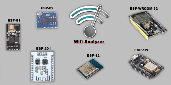


Do you know about the WiFi signal strength from an ESP? Have you ever thought about getting an ESP01, which has a small antenna, and put it inside a socket? Will it work? To answer these questions, I performed several tests comparing various types of microcontrollers, including ESP32 with ESP8266. We evaluated the performance of these devices at two distances: 1 and 15 meters, both with a wall in between.
All this was performed just to satisfy my own curiosity. What was the result? This was a highlight for ESP02 and ESP32. I will show you all the details in this video below. Check it out:
In addition to the results when comparing the ESP chips, I will tell you today about how to program different ESP chips as Access Points (each on a different channel), how to check the signal strength of each through an application on the smartphone, and finally, we are going to make a general analysis about the signal strength of the networks found.
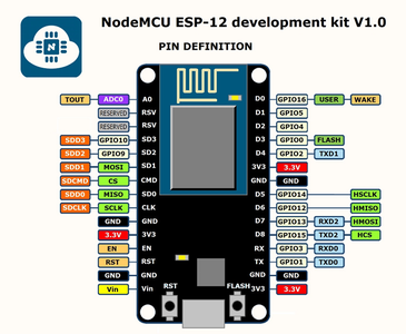
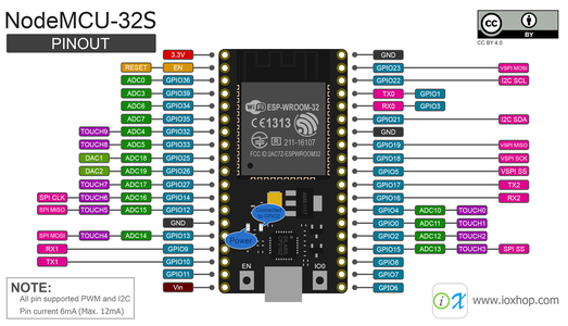
Here, we put the pinning of each of the microcontrollers we analyzed:
Step 1: WiFi Analyzer


WiFi Analyzer is an application that finds WiFi networks available around us. It also shows the signal strength in dBm, and the channel for each network. We will use it to do our analysis, which is possible through visualization in the modes: list or graph.
PHOTO APP --- The app can be downloaded from the Google Play Store through the link:
https://play.google.com/store/apps/details?id=com.farproc.wifi.analyzer&hl=en
Step 2: But How Can I Program ESP Chips That Do Not Have USB Input?
To record your code on ESP01, watch this video "RECORDING ON ESP01" and see all the necessary steps. This procedure is a useful example, as it is similar to all other types of microcontrollers.
Step 3: ESP02, ESP201, ESP12

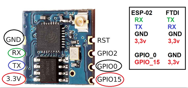
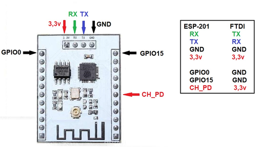

Just like in ESP01, you will need an FTDI adapter to record, like the one above. The following is the link required for each of these ESPs.
IMPORTANT: After recording the program in ESP, be sure to remove the GPIO_0 from the GND.
Step 4: Libraries

If you choose to use ESP8266, add the following "ESP8266WiFi" library.
Simply access "Sketch >> Include Libraries >> Manage Libraries ..."
This procedure is not necessary for ESP32, since this model already comes with its library installed.
Step 5: Code
We will use the same code in all ESP chips. The only differences between them will be the name of the access point and the channel.
Remember that ESP32 uses a library that is different from the rest: "WiFi.h". The other models use the "ESP8266WiFi.h".
* The ESP32 WiFi.h library comes bundled with the board installation package in the Arduino IDE.
//descomentar a biblioteca de acordo com seu chip ESP
//#include <ESP8266WiFi.h>  //ESP8266//#include <WiFi.h> //ESP32
Step 6: Initial Settings
Here, we have the data that will change from one ESP to another, the ssid, which is the name of our network, the network password and, finally, the channel, which is the channel where the network will operate.
/* Nome da rede e senha */
const char *ssid = "nomdeDaRede";
const char *password = "senha";
const int channel = 4;

/* Endereços para configuração da rede */
IPAddress ip(192, 168, 0, 2);
IPAddress gateway(192, 168, 0, 1);
IPAddress subnet(255, 255, 255, 0);
Step 7: Setup
In setup, we will initialize our access point and set the settings.
There are details for the constructor where we can define the CHANNEL in which the created network will operate.
WiFi.softAP (ssid, password, channel);
void setup() {
  delay(1000);
  Serial.begin(115200);
  Serial.println();
  Serial.print("Configuring access point...");
  /* Você pode remover o parâmetro "password", se quiser que sua rede seja aberta. */
  /* Wifi.softAP(ssid, password, channel); */
  WiFi.softAP(ssid, password, channel);

  /* configurações da rede */
  WiFi.softAPConfig(ip, gateway, subnet);

  IPAddress myIP = WiFi.softAPIP();
  Serial.print("AP IP address: ");
  Serial.println(myIP);

}

void loop() {
}
Step 8: Experiment
1. All chips were connected simultaneously, side by side.
2. The experiment was performed in a working environment, with other networks available, so we might see other signs next to ours.
3. Each chip is on a different channel.
4. Using the application, we check the graph generated according to the intensity of the signal, both near the chips and in a more remote environment with walls in the way.
Step 9: Analyzing Signs

Close to chips - 1 meter
Here we show the first notes of the application. In this test, the best performances were from ESP02 and ESP32.
Step 10: Analyzing Signs

Away from the chips - 15 meters
In this second stage, the highlight again is the ESP02, which has an external antenna of its own.
Step 11: Bar Graph - 1 Meter Away
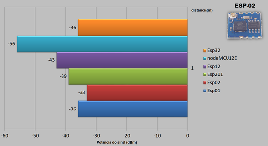
To facilitate visualization, we set up this graph that indicates the following: the smaller the bar, the more powerful the signal. So here again, we have the best ESP02 performance, followed by ESP32 and ESP01.
Step 12: Bar Graph - 15 Meters Away
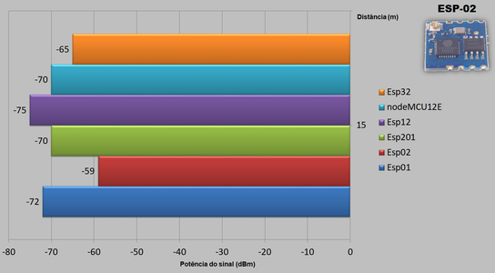
In this chart we return to the best performance of ESP02, followed by ESP32 over a longer distance.
Step 13: Channels

Now, in this image , I'll show you how each chip is operating on a different channel.
Step 14: Conclusions
- ESP02 and ESP32 stand out when we analyze the
signal, both while near and when farther away.
- ESP01 is as powerful as ESP32 when we look closely, but as we move away from it, it loses a lot of signal.
The other chips end up losing more power as we pull away.


