

Introduction: ESP8266 Wiht DS1307 RTC, NV SRAM and Square-Wave Output Signal


The DS1307 is real time clock (RTC) with
plus 56 bytes of NV SRAM. Address and data are
transferred serially through an I2C bus.
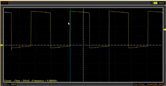
Additional functionality is programmable Square-Wave output signal.
You can set four frequency (1Hz, 4kHz, 8kHz, 32kHz) on the SQW/OUT pin.
Download library RTC_DS1307 for Arduino IDE
Step 1: Components
- ESP8266 12e V3
- DS1307
- Few wires
Step 2: Connect the DS1307 to ESP8266

Step 3: Setup Frequency on the SQW/OUT Pin


To set the frequency, use this function:
- rtc.SQW( f1hz );
- rtc.SQW( f4096hz );
- rtc.SQW( f8192hz );
- rtc.SQW( f32768hz );
#include "ESP8266WiFi.h"	#include "Wire.h"
	#include "RTC_DS1307.h"

	RTC_DS1307 rtc;

	void setup() {
	  Serial.begin(115200);
	  Serial.println("");
	  Serial.println("START");

	  Wire.begin();

	  rtc.SQW( f32768hz );
	}

	void loop() {
	}
Step 4: Setting the Time on DS1307

//byte second, byte minute, byte hour, byte dayOfWeek, byte dayOfMonth, byte month, byte year
Setting the time on DS1307
rtc.SetTime( 00, 40, 13, 1, 06, 03, 17 );
In the loop we will read time from DS1307
void loop() {
  //Read time from DS1307 and display (You must be connected to the serial port to see results)
  rtc.DisplayTime();
  //Convert time to unix timestamp
  long uts = rtc.UnixTimestamp();
  Serial.println( uts );
  delay(1000);
}
Step 5: Write and Read NV SRAM

DS1307 has 56 bytes of NV SRAM for general use. For example, you can store configuration data.
In our case, we write and read String.
void setup() {
  Serial.begin(115200);
  Serial.println("");
  Serial.println("START");

  Wire.begin();
//Write in NV SRAM
rtc.WriteRAMStr(0, "http://geek.adachsoft.com/");
delay(500);
//Read from NV SRAM
String str = rtc.ReadRAMStr(0);
Serial.println("RAM: " + str);
}void loop() {
}


