

Introduction: Earth Globe Rotating With Arduino or Raspberry Pi Controlled Stepper Motor


This instructable describes how to upgrade your globe to a motorized version. It looks amazingly better on the shelf when it is slowly rotating, and any demonstration with your kids (to explain the day/night cycle or the seasons) will gain in interest. No need to rotate the globe by hand while painfully holding the flash light with your teeth.
The instructions correspond to the various parts I had at my disposal so they may have to be adapted to yours. The needed parts are:
- a globe, the one I used is this one ($30) http://www.amazon.com/Elenco-11-Desktop-Political...
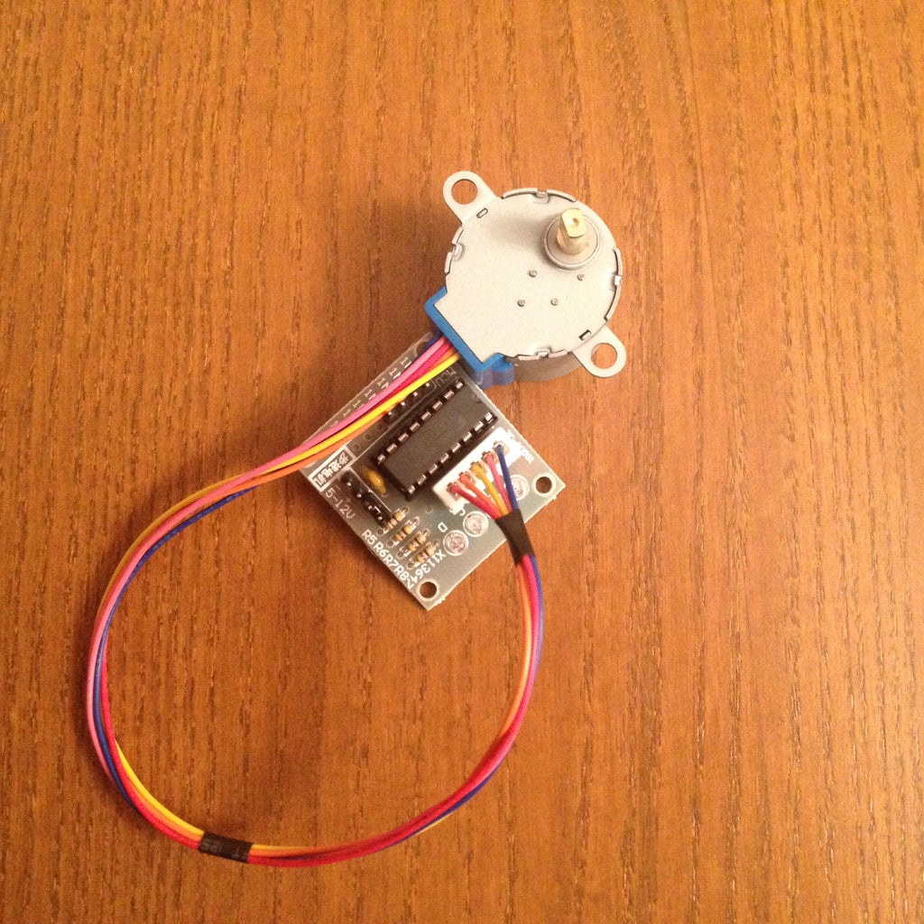
- a stepper motor + driver. This one is great because it is geared down conveniently for the kind of torque/speed we want ($6) http://www.amazon.com/gp/product/B00DUSYEWY
- an arduino or raspberry Pi (see link bellow)
- some axle + wheel from a lego box or such. The axle I use is ~1/4" diameter and was a left over part from a kit, http://www.amazon.com/Thames-Kosmos-665068-Solar-M...
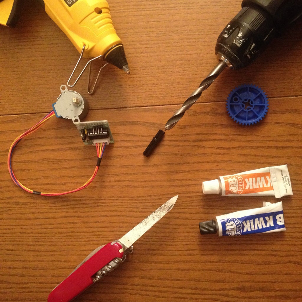
- various tools, such as a saw or knife, a drill, glue (hot glue is optional),...
- but you do want a very strong epoxy JB-Weld that sets in 4 minutes (explanations in step 4), such as this one http://www.amazon.com/J-B-Weld-8276-KWIK/dp/B0006O...
I will not describe the operation of the motor since it is very well done in this instructable: https://www.instructables.com/id/BYJ48-Stepper-Moto... you might want to check it out first since some of the steps bellow are better carried out if the motor is powered and rotating.
Step 1: Flush the Globe Axis With the Rotating Plate

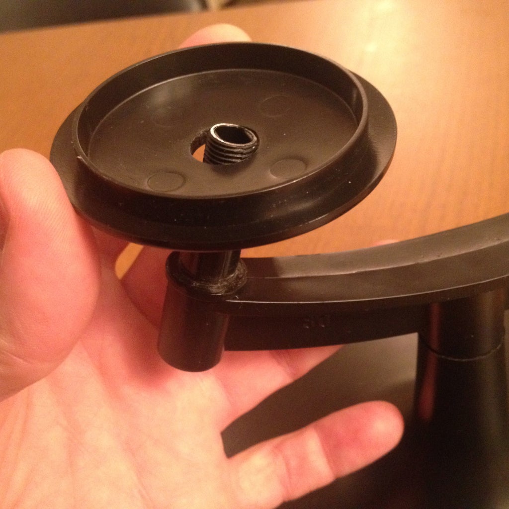
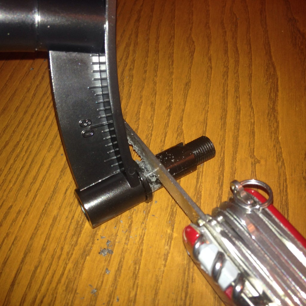


This globe, rests onto a plate that can be taken out. Take it out. The large axis that protrudes has to be cut so that the plate will be flush with it when resting on its position. After you cut the axis (leaving 2-3mm of protrusion), place the plate back on its stand. It should rotate freely. If not, shave the small plastic fibers (left over from the cut) with a knife.
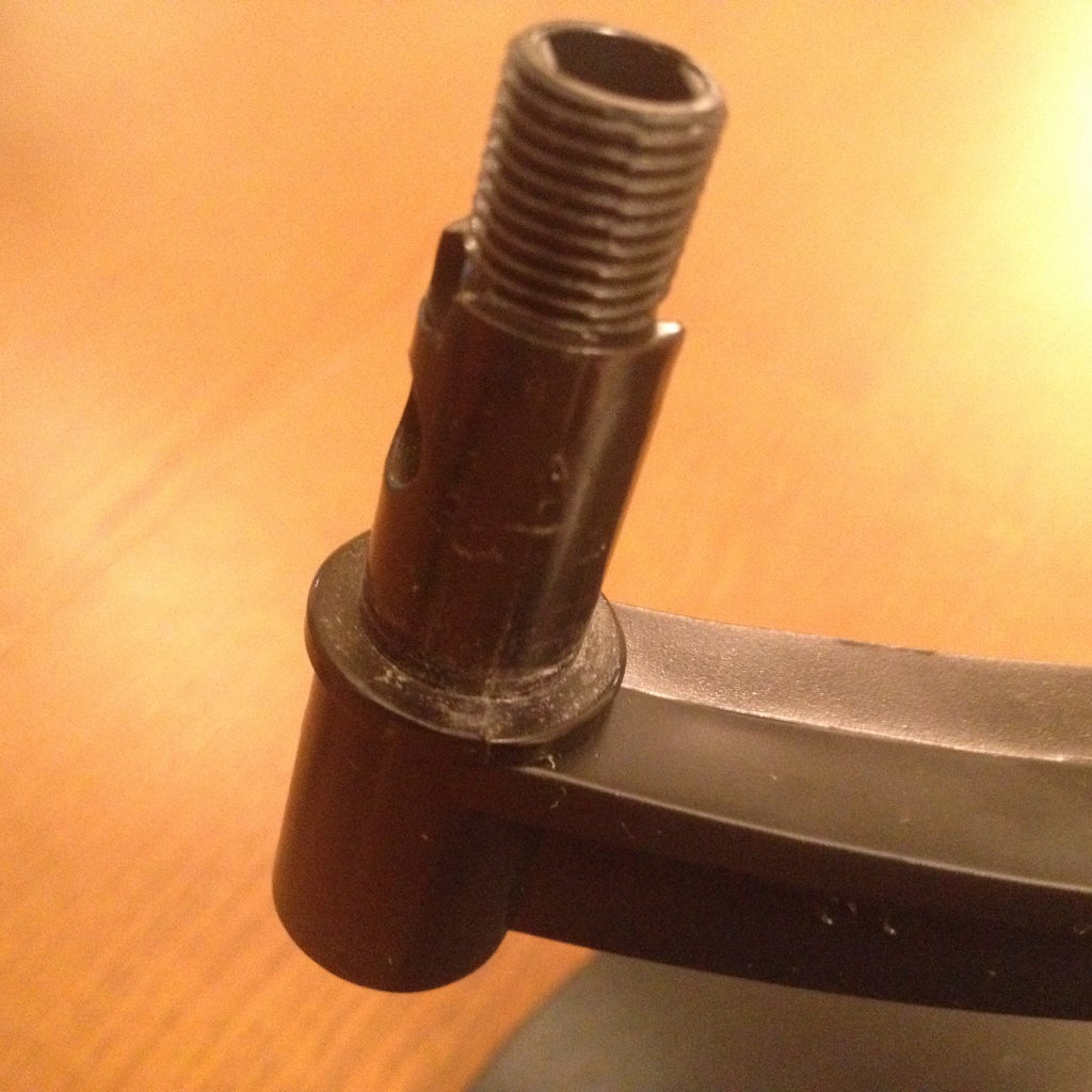
Step 2: Drill the Base of the Arm for Your Wheel Axle


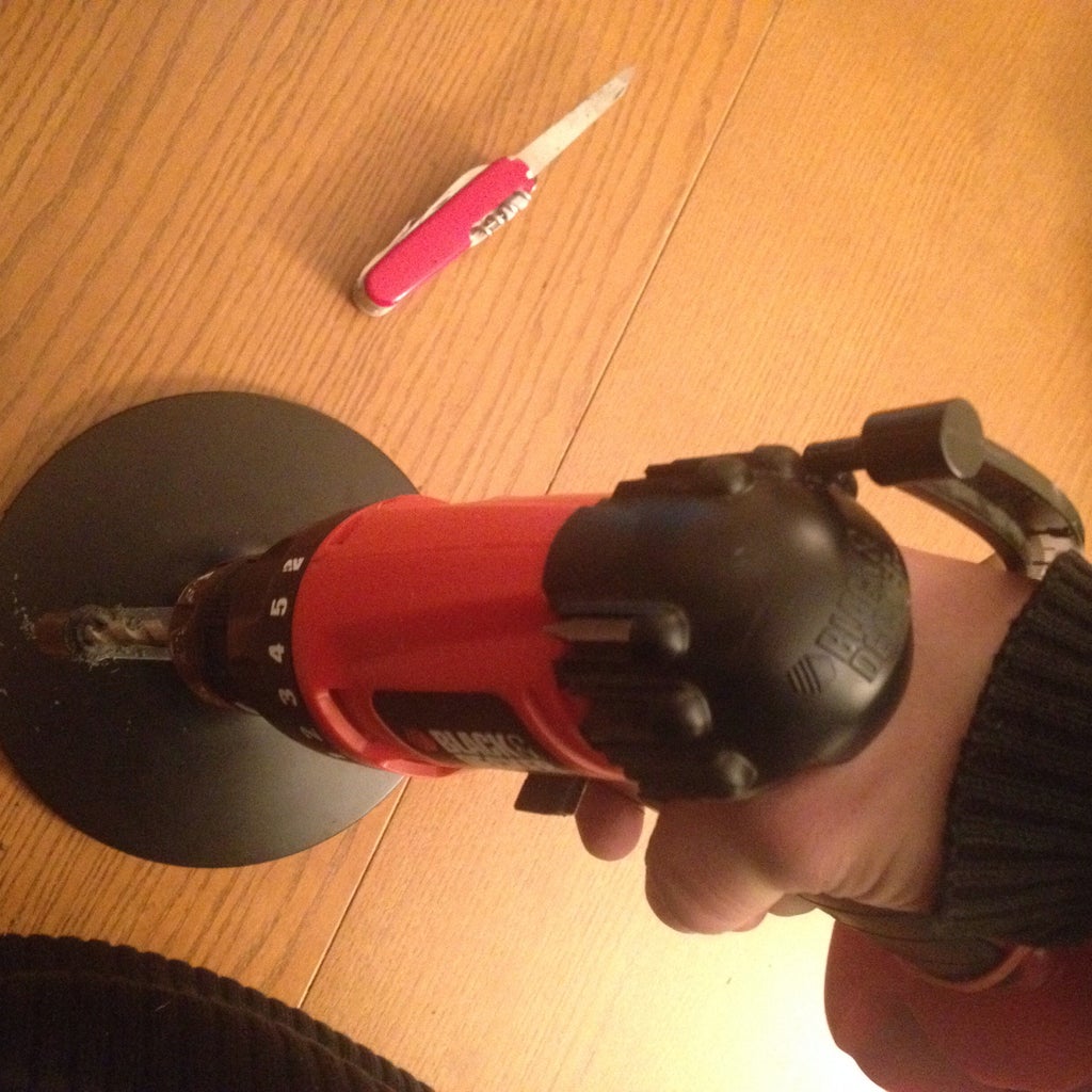

The globe axis that we just cut is actually hollow on this globe. But the hole is not circular and to small anyway for the wheel axle I have.
Find a drill bit with a diameter that corresponds to the wheel axle you have. If you have another one, slightly smaller, use it first. You want the drill to be well guided by the existing hole, and using the smaller drill bit may help you in this task. Also, be careful to not damage the plastic part by going to fast.
The most important part is to stay on axis. Do not drill if you are forced to be off axis. Prefer to drill from the top by bending slightly the globe arm away, it might actually guide you since the top part of the arm is precisely on the rotation axis.
Step 3: Glue the Wheel in the Plate
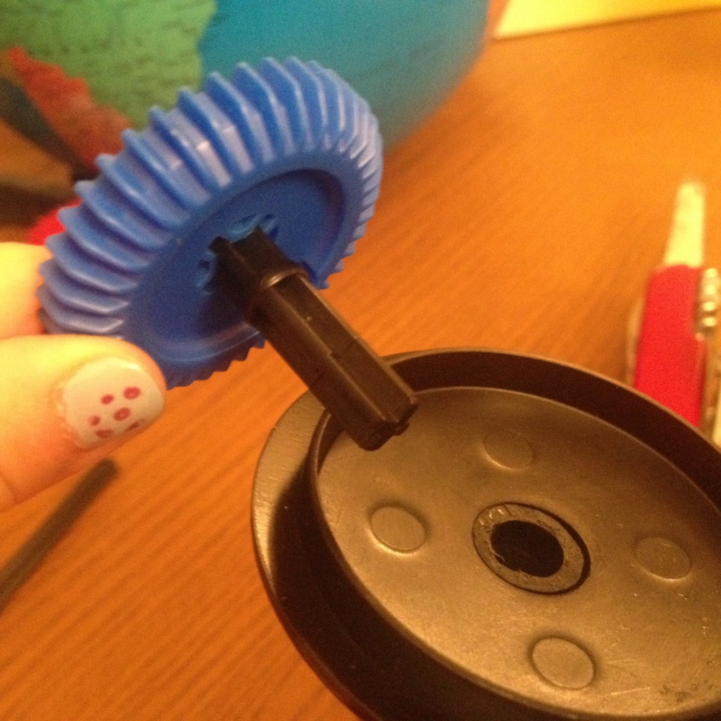


Set the wheel on its axle. then fit the axle into the hole through the plate. It should rotate freely, without much play.
At that point, you can glue the wheel in the plate. I used hot glue, just in case I would want to take the wheel back out, but a few drops of epoxy would do it.
Step 4: Glue the Wheel Axle on the Motor Axis


This is the tricky step here. Usually, gluing two axles end-to-end is not a great idea since a lots of torque and constraints can develop at that point and most glues would fail quickly. This is why we need a very strong JB-Weld epoxy which is going to harden into a sturdy piece of polymer, anchoring the motor axis to the wheel axle.
We need to use the 4-minute epoxy because it quickly becomes not sticky, and doesn't drip. For a short period of time (~1 minute) we will be able to adjust the two pieces on the same axis by inserting the still hardening assembly into the globe axis. The glue will not drip and stick the axle into the globe axis at that point.
- Put equal part of the epoxy components on a sheet of paper and mix thoroughly with a stick. Wipe the stick clean, and continue stirring. This ensures you get rid of un-mixed components that stay around the stick and could badly weaken this mighty solid polymer we are trying to produce.
- Dip one end of the axle into the glue. With the stick, force some of the glue into the corners of the axle in order to insure a good anchoring. The glue should cover ~1/4" of the tip. Wipe the excess glue that protrudes out of the axle diameter (since it will later need to rotate freely in the hole you just drilled).
- Dip the tip of the motor axis in the epoxy. It should almost not drip at all. Avoid the glue from reaching the motor because if any makes it in the gears, you can just ditch your motor.
- Put the axle in contact with the motor axis, maintaining them aligned. Eye-balling at that point is ok.
- At some point, you will feel that the glue is becoming harder by the second. You can actually ask someone to help you by gently stirring the leftover glue on the sheet of paper. Since it is a chemical reaction between the two components (and not really a "drying"), it will harden the same on the paper or on your setup. When the glue becomes hard to stir on the paper, you have less than a minute to do the following.
- Insert the axle+axis setup into the globe, bringing the motor flush with the globe arm. Plug the base plate into the axle and maintain the whole setup tightly with one hand, e.g. pressing the motor upward with your thumb and the wheel and its axle downward with your other fingers.
- With your other hand, you can rotate gently the the globe arm around your hardening setup. This will ensure mechanically that 1) the glue won't stick into the globe axis, 2) the axle sets into a position respecting a correct alignment that allows a constraint-free rotation.
- Keep it like this for a few minutes, then, gently push down the axle (through the wheel) and take out the newly assembled axis+axle.
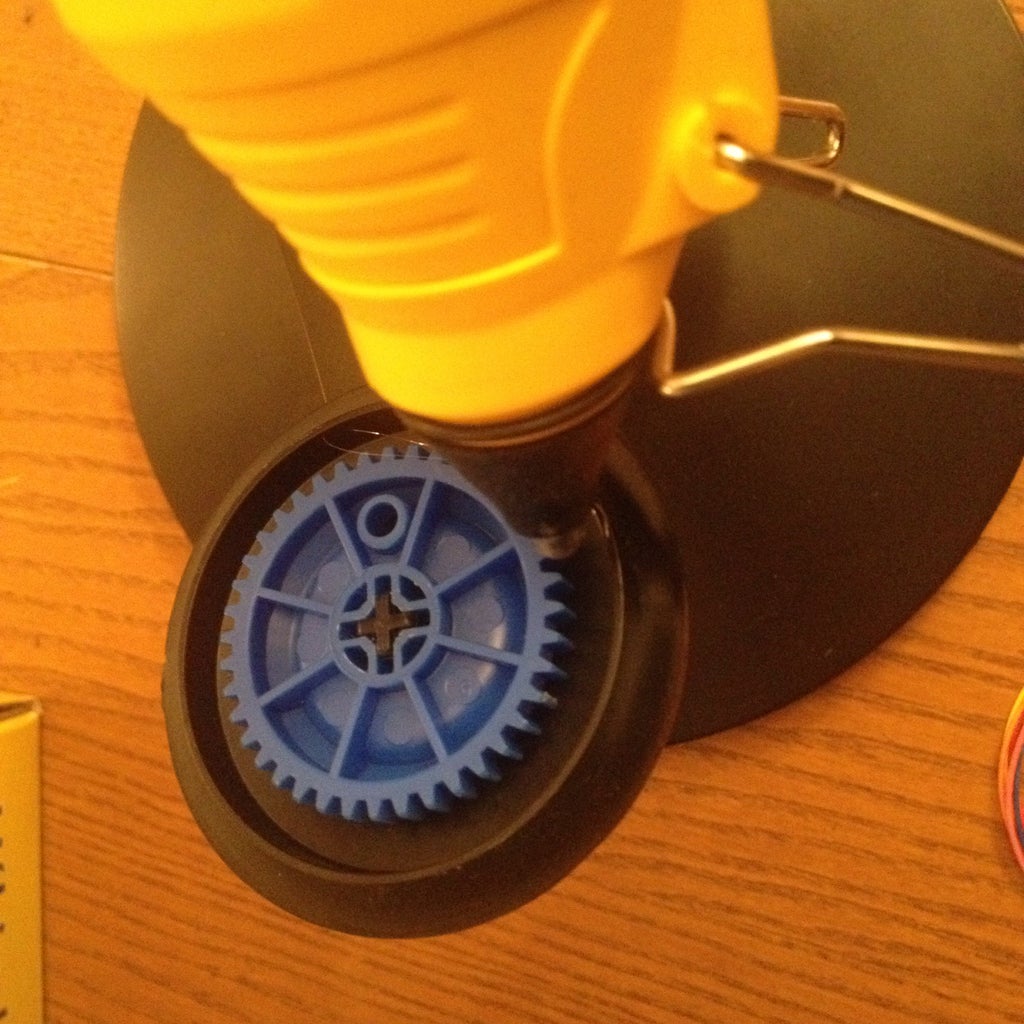
Step 5: Glue the Motor in Place


The axle is glued to the motor axis. Let it set a few more minutes before applying any sort of torque.
By that point, you might want to have the motor ready to be powered and have the axis rotating slowly. If needed, check this instructable: BYJ48 Stepper Motor
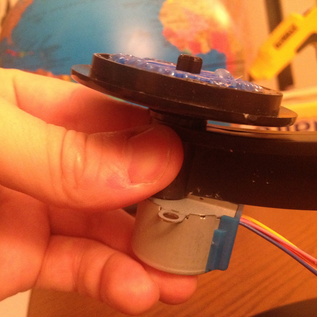
Insert the axis in the globe and plug the base plate on the axle. Glue the motor to the globe axis, a few drops of epoxy should do it. Don't use hot glue since the motor could get warm at times and un-glue itself away.
While gently maintaining the motor up, turn it on. The spinning will ensure that the motor sets into a position that respects the correct alignment necessary to a constraint free rotation.
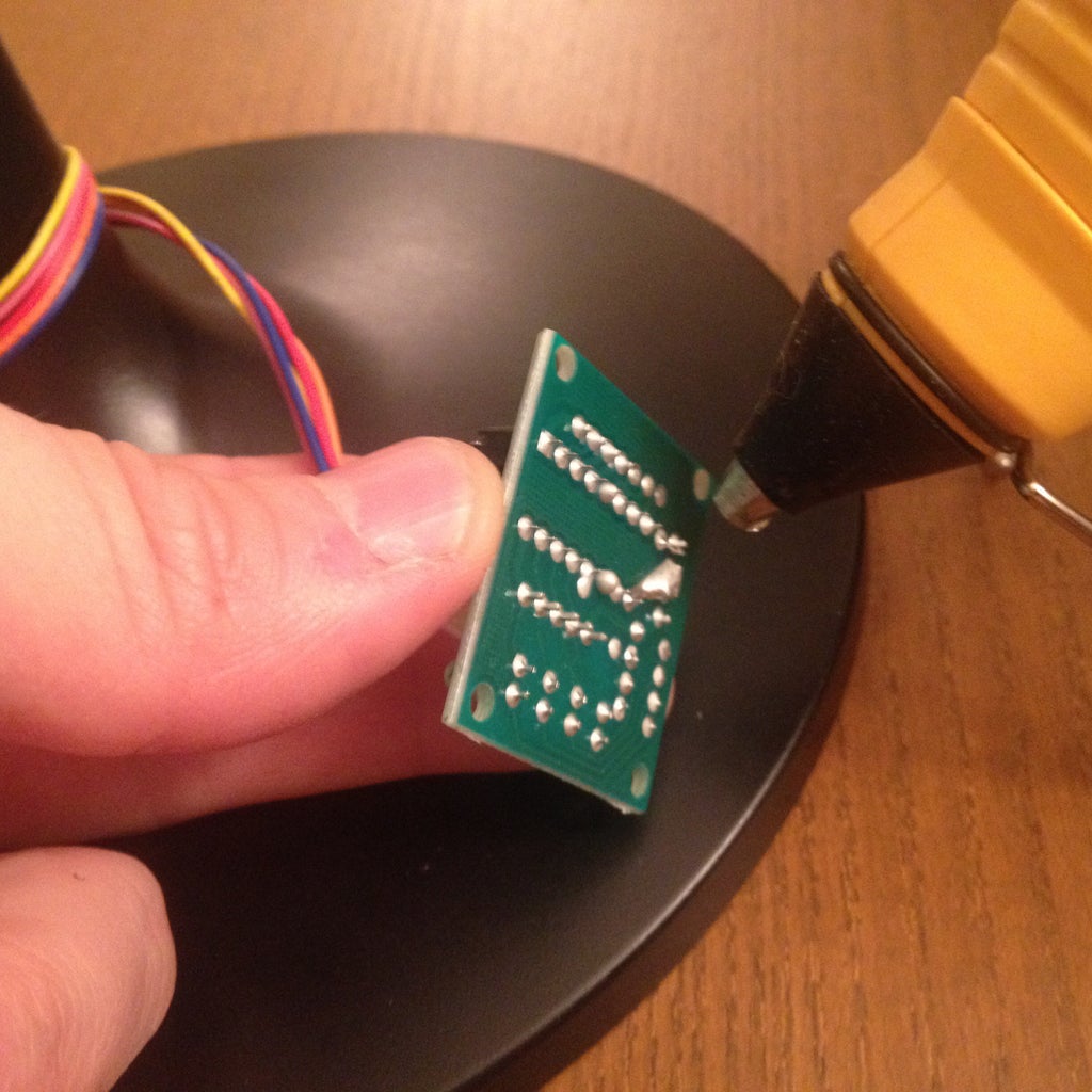
Step 6: Glue the Driver on the Base
Enjoy
The attached code can be loaded on an Arduino to operate the motor.
#define IN1 8
#define IN2 9 #define IN3 10 #define IN4 11 void setup() { pinMode(IN1, OUTPUT); pinMode(IN2, OUTPUT); pinMode(IN3, OUTPUT); pinMode(IN4, OUTPUT); }uint64_t timeMultiplier = 24 * 60 * 1; // that gives you ~ one rotation per minute.
uint64_t msPerDay = 24ULL * 3600ULL * 1000ULL; uint64_t divideForStep = 64ULL * 48ULL * timeMultiplier; double nextTimeStep = 0;
void loop() { static unsigned long zeroTime = millis(); uint64_t curTime = millis() - zeroTime; if(curTime * divideForStep > nextTimeStep) { nextTimeStep += msPerDay; stepper(true); } }
inline void stepper(bool normalRotation) { static int Steps = 0; Steps += 8 + (normalRotation ? 1 : -1); Steps %= 8; switch(Steps) { case 0: digitalWrite(IN1, LOW); break; case 1: digitalWrite(IN3, HIGH); break; case 2: digitalWrite(IN4, LOW); break; case 3: digitalWrite(IN2, HIGH); break; case 4: digitalWrite(IN3, LOW); break; case 5: digitalWrite(IN1, HIGH); break; case 6: digitalWrite(IN2, LOW); break; case 7: digitalWrite(IN4, HIGH); break; default: break; } }

Participated in the
Supercharged Contest

Participated in the
Makerlympics Contest


