

Introduction: Flip Machining on the DMS CNC Router


After thinking about the potential of 3-axis flip machining, I decided to construct a three-dimensional relief painting out of laminated plywood. This piece would be viewable from either side, and though the two sides would be related to one another, they wouldn't necessarily align.
In this Instructable, I'll discuss my concept and detail my step-by-step process.
I played around with a few different image concepts before deciding to use a background based on the texture of the Romanesco broccoli. With its interlocking, scalable fractal pattern, this texture would certainly create an interesting background for both sides of the painting. From that point, I began looking at sketches created by children as source imagery. Because this CNC project deviates far from the norm--it's not intended to be functional and it won't be mass-produced--I was curious to see how it would evolve if my initial steps were haphazard, spontaneous, and intuitive. In a setting in which process is usually determined by predetermined outcomes, what would happen without a specific end goal? To that end, I decided to push the possibilities of the gesture as it relates to the machine.
In art school I had become accustomed to generating 30-second to 60-second gesture drawings of the nude figure, and sometimes really surprising things happened out of that process. The idea was to produce in bulk, and then sort through the piles of drawings to find the ones that really hit on something--an effortless line that communicates movement, a flick of a wrist that charges a hunched-over figure with emotion. I began doodling with my mouse on the computer, lightly referencing the Romanesco but mostly working with quick, messy scribbles for a few seconds and then stopping. I produced at least twenty drawings, and selected two for the front and back of my CNC project.
Step 1: ArtCAM Model Generation


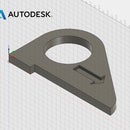
Once I had selected my Romanesco background and two drawings, I opened ArtCAM and created a new model at 48" x 24" x 6". For the front relief, I used the vegetable as a texture and then used a two-rail spline to torque the relief in a twisted, "flying carpet" shape. Working with depth in this way is a good way to capitalize on CNC capabilities. I made sure that this relief was only 42" x 18" (not worrying too much about z at this point) so that I would have a 3" border on all sides of my material when I went to machine my part. This would give me a surface to rest the part on after completing the flip. I then converted my first drawing into a relief in which the darker areas would recede while the lighter areas would come forward. I went back-and-forth between ArtCAM and Gimp to dial in the gradient, until the relief had a nice variety of raised lines. I then went through this same process for the back relief, offsetting it by 0.75" below the front relief and making sure the "raised" areas were pointing down--in other words, ensuring that my model would never be thinner than 0.75".
Once I was happy with the look of both sides, I used the scale function to ensure that the difference between highest and lowest z values for both front and back was 5". I set my zero to the bottom left corner of the model, and made sure my front relief spanned z = 6 to z = 1. Then (after copying and saving the back relief as a layer in case I made a mistake) I mirrored the back along the axis that I would use flip the part. In this case, I would be flipping the part in the same way you would turn the page of a book, from right to left across the y-axis. I then inverted my z values for the back, and set it from z = 5.75 to z = 0.75. It took some time to sort through this in my mind--to ensure that I wouldn't accidentally machine into my front side--but it really helped to work with simple numbers. I then saved this model.
Step 2: Toolpathing


I decided to use a 1" end mill with a stepdown of 0.5" and a stepover of 0.325" for both sides as a parallel roughing toolpath. This would remove a lot of material quickly and efficiently. However, because the end mill I planned to use was only 4.5" in depth, I made sure to stop my toolpath at a z level of 1.8" (remember my zero is at the bottom of the model). To finish the roughing pass, I used a 1" ball end mill with the same stepover and a stepdown of 0.2"--this tool was over 7" long. I used the same ball end mill for both finishing paths, stepping over 0.1" each time.
To square my part, I created a toolpath that would go 0.125" into a spoiler board. This path would trace the outline of the material onto the board and allow me to set my zero. Then, after setting my material down, I would use another toolpath to square the top to the bottom. I went from z = 6 to z = 4 in stepdowns of 0.5". That way everything would align properly when I flipped my part. After simulating my toolpaths, I post-processed them and reviewed the code to make sure there weren't any problems.
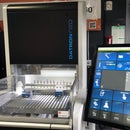
Step 3: Setting Up the Machine and Machining the Front Side


I took a picture of my toolpaths in ArtCAM and kept a detailed set of notes to ensure that I knew which six-digit .PIM file corresponded to which toolpath. I then cut a 5' x 4' spoiler board out of plywood and clamped it to the DMS CNC table. Then, after doing some dry runs, I set my TCP offsets and took a picture of the machine coordinates. This was an essential part of the process! I then ran my first toolpath--the outline into the spoiler board. Then I set down my material and used blocks to screw it into the spoiler board. This was a nice system because I didn't have to worry about my spindle colliding with a clamping system. Going back in time for a second, my material was made from 8 sheets of laminated birch plywood, 2' x 4' x 0.75". I did the glue-up in three parts to make sure I had enough time for each step--I did the two halves and then glued them together. This was challenging to do at this kind of scale.
Back to the CNC machine. I squared the material, and then the run began. I ran the first roughing pass at around an 80% feed rate, which was aggressive but it worked. This took about 2.5 hours. The finishing pass took about 1 hour, and then I eagerly opened the doors and vacuummed out all the sawdust (it was hard to see progress as I went because of all the dust--see picture above!).
Everything went swimmingly! There were a few blow-outs but in general the material and resolution worked quite well.
Step 4: Flipping the Part and Maching the Back Side


This was the scary part--would everything align properly or would I machine into my front side?
I had shut down the machine over the weekend, so when I got back I removed my part, cleaned up the spoiler board, and flipped the material over. I aligned it with the toolpath in the spoiler board and used the same blocks to screw it into place. Then, I used Manual Data Input to bring the spindle head to the machine x and y coordinates that corresponded with my zero point. I set my x and y TCP offsets from there. Then, I moved x and y and touched the tool down to the spoiler board, and set my z TCP offsets.
I ran the roughing and finishing passes at similar speeds compared to the front side. I found it difficult to see what was happening, again because of the sawdust, but as time went on I became more confident that everything was working according to plan. When everything was done, I vacuumed away the dust and revealed the back side!
Step 5: Cutting Off the Shoulders and Cleaning Up the Part

I cut off one shoulder on the table saw in the woodshop. After realizing I now didn't really have a surface to place against the fence, I used the bandsaw for the other three sides. I then sanded my edges and cleaned up the blown-out parts of the contour with a dremel tool.
The piece turned out to be an unexpected, contour-riddled landscape that seemed quite far from the initial impetus to create the work. This piece is a good candidate for painting, though I do like the way the topography is highlighted by the plywood veneer. It would also make an interesting mold for larger-scale reliefs. As my residency at Pier 9 continues, I'm looking forward to seeing how this process provides a springboard for future work.

Participated in the
CNC Challenge


