

Introduction: Fun and Games With Micro:bit: Catapult and Operation!


(Hi! I'm participating in the After School Challenge. If you like my instructable, your vote will be very appreciated. Thanks, and have a great day!)
Micro:bit is a friendly electronic board developed by the BBC, to teach kids about electronics, coding and other STEM topics. And also, it is great to create some fun activities in the classroom and in after school clubs!
In this Instructable I will teach you how to use Micro:bit to create two games: a servo-triggered Catapult and an electronic Operation game. Materials are easy to get (most of them are reused) and you don't need special tools to assemble the components (like a rotary tool or a soldering iron.)
Alright, let's have some fun!
Step 1: Micro:bit Catapult

Introduction:
Catapults are probably the most famous siege machine of all times. During medieval times, these large and powerful machines were used by armies to break the defenses of an enemy city, throwing projectiles like stone balls, iron arrows, baskets of venomous snakes, flaming barrels, rotten corpses, syrupy chemicals and cattle manure.
In this lesson, students will apply basics of mechanical engineering to create a catapult. The trigger will be the A button from the Micro:bit, and the release mechanism will be the servo motor. At the end, students will be challenged to a basketball game, where they will try to launch a ping pong ball inside a trash bin.
The BBC Micro:bit has several digital pins where you can connect electronic components to add new functions to your board. We will explore how to use the servo motor, so we can add some movement to our technological creation.
Fun Facts:
- The word “catapult” comes from the Ancient Greek, meaning "to toss, to hurl".
- Several catapults, like the “ballistae” variety, were very impractical to transport to the battlefield, so armies used to construct them on the siege site instead.
- Armies stopped using catapults due to the inventions of gunpowder and cannons. However, a modern day use is the “aircraft catapults” that are used to launch planes from land bases and sea carriers when the takeoff runway is too short for a powered takeoff.
Definitions:
Catapult: a siege weapon that uses the sudden release of stored potential energy to propel its payload.
Force: To drive or propel against resistance.
Servo (servo motor): component that integrates a motor, a gear box and a sensor to control the position of the shaft.
Tension: the pulling force of one object on another object.
Trajectory: The path of a flying object moving under the action of a given force.
Step 2: Materials

- 1 BBC Micro:bit board
- 1 2 AAA Batteries holder with plug for Micro:bit
- 2 AAA Batteries
- 1 USB cable for Micro:bit
- 1 Servomotor with double-arm horn and screw
- 3 Alligator Test Leads (red, black and blue)
- 3 Jumper wires (red, black and blue)
- 1 Mounting Tape (double-sided scotch)
- 1 Insulating tape
- 1 pair of scissors
- 1 screwdriver
- 1 cardboard box (18cm x 18cm x 5cm approx.)
- 2 craft sticks
- 1 bending clip (32mm)
- 1 plastic spoon (resistant to tension and torsion)
- 3 zip ties
- 1 rubber band
- 1 ping-pong ball
- 1 ruler
- 1 pencil
- 1 Computer with internet access or Makecode offline editor installed.
Before the lesson:
- Make bags with the materials to distribute later to each kid.
- Verify that your classroom has access to internet. If not, download and install the offline Makecode app on each computer.
- Make a prototype of this project, so you can show it to the students.
Step 3: Starting the Mechanical Part


Take one craft stick, measure 9 cm and cut it in that point.
Step 4: The Servo


Attach the servo motor to one of the ends of the craft stick using a piece of mounting tape. Tape it using the side of the servo without the sticker. Then fasten the servo using a zip tie.
Step 5: The Trigger


Attach the double-arm horn to the servo’s shaft using a screwdriver. Before inserting the screw, verify that the bigger arm of the horn can rotate 180 degrees from right to left at the side of the craft stick.
Step 6: The Frame


Using mounting tape, stick the other end of the clear side of the craft stick to one side of the box. There must be a 4 cm portion of the craft stick from the border of the box to the end near the servo.
Step 7: Arm and Bucket


For the catapult, firmly attach the spoon to one of the handles of the bending clip. Use the insulating tape and fasten it with a zip tie.
Step 8: The Frame


Now, attach the craft stick to the available handle of the clip. Use the insulating tape and fasten it with a zip tie. When both zip ties are completely pulled, cut the remaining parts.
Step 9: Putting Everything Together


Using the mounting tape, stick the catapult perpendicularly to the servo’s craft stick.
Step 10: Mechanical Test


Test the release system. Verify that you can lock the spoon using the big arm of the servo, and that you can trigger the catapult rotating the same arm.
Step 11: Wires


Now we will do the electrical connections. Take the jumper wires and insert a red one in the socket of the servo’s red cable; the black one in the socket of the servo’s brown cable; and the blue one in the socket of the servo’s orange cable.
Step 12: Connecting the Micro:bit

Using the alligator cables, connect the black jumper wire to the GND pin of the Micro:bit; the red jumper wire to the 3V pin, and the blue jumper wire to the digital pin 0. To organize the cables in a better way, you can tie them with a rubber band.
Step 13: Batteries


Insert the batteries in the battery holder, plug it to the Micro:bit and stick the battery holder to the box using mounting tape.
Step 14: Coding


- Students must open Makecode and click in “New Project”.
- Click the word "untitled" and rename your project "Catapult".
- Explain to the students that the Micro:bit has three digital pins in its basic form: 0, 1 and 2 (there are 21 in total, from P0 to P20, but the rest will be left for a more advanced level). Also, there are a 3V pin and a GND (ground) pin to power some special electronic components. The servomotor will be connected to the pins 3V and GND to power it, and to the pin 0 to control it.
- From the “Advanced” option, open the “Pins” group of blocks and bring the “Servo write pin P0 to 180” block. Change 180 to 90. These are the number of degrees we want our servo to rotate when the program starts.
- From the “Basic” group we will bring the “show string ‘Hello!’” block and place it under the “Servo write pin” block. We will write “Catapult” instead of “Hello!”. Then, also from “Basics” we will bring the “show icon” block and select “diamond”.
- We will delete the “forever” block (you can drag it to the right, or right click over it and select the “delete block” option). Instead, we will bring from the “Input” group the “On button A pressed” block.
- Return to the Advanced options, “Pins” group of blocks, and drag the “servo write pin P0 to 180” block. Placed it inside the “on button A pressed” block. This part of the program will move the servo from the 90 degrees position to the 180 degrees position, to release the catapult.
- Next block to place: “show icon” from “Basic”, and select the “target” icon.
- To return the servo to the original position, we will go to the “Pins” group of blocks, and drag the “servo write pin P0 to 180” block, changing its value to 90. Also, we will bring a “show icon” block from basics, choosing “diamond”.
- Press the “Download” button to download your code as a .hex file. When you download the code, it gets compiled from Javascript into ones and zeros that the Micro:bit can store and execute. You can find the code in the “download” folder of your computer. Drag the downloaded code over to your Micro:bit, just like dragging and dropping a file to an external drive or USB stick. You should see a yellow LED flashing next to your USB. This means the code is being transferred. When the LED finishes flashing, the program is fully downloaded.
Step 15: Test the Whole Device!

The catapult is ready for action.
Students may test it and play a basketball game using a basket or an empty and clean trash bin.
At the end of the lesson, students must return to the teacher the Micro:bit, the servo motor, the cables, the battery holder and the batteries.
Step 16: Operation Game With Micro:bit

Introduction
A surgical instrument is a specially designed tool or device for performing specific actions or carrying out desired effects during a surgery or operation, such as modifying biological tissue, or to provide access for viewing it. Over time, many different kinds of surgical instruments and tools have been invented. Some surgical instruments are designed for general use in surgery, while others are designed for a specific procedure or surgery. Accordingly, the nomenclature of surgical instruments follows certain patterns, such as a description of the action it performs (for example, scalpel, hemostat), the name of its inventor(s) (for example, the Kocher forceps), or a compound scientific name related to the kind of surgery (for example, a tracheotome is a tool used to perform a tracheotomy).
Inspired by this kind of medical tools, in 1964, an industrial designer named John Spinello created a popular and game for kids, that uses electrical conductivity to test players' hand-eye coordination and fine motor skills: “Operation” uses electrical conductivity to detect if a player can extract an “organ” from a cavity. If the pincers touches the borders, a buzzer will sound and the nose of the “patient” will light on, and the player loses the match.
In this lesson, students will apply basics of electrical engineering to recreate the classic Operation Game. Micro:bit has several digital pins where you can connect electronic components to add new functions to your board. We will explore how to use the Mini Speaker, so we can add some sounds to our technological creation. Kids will try to remove little plastic items from the three cavities. If the hair clip touches the bed, it will be game over.
Fun Facts
- The Operation game is a variant on the old-fashioned electrified wire loop game popular at funfairs around the United States. It consists of an "operating table", lithographed with a comic likeness of a patient (nicknamed "Cavity Sam") with a large red lightbulb for his nose.
- The real life equivalent of the Operation game pincers is the surgical instrument Forceps, that are a handheld, hinged instrument used for grasping and holding objects. Forceps are used when fingers are too large to grasp small objects or when many objects need to be held at one time while the hands are used to perform a task.
- Surgical Instrumentation is the activity of providing assistance to a surgeon with the proper handling of surgical instruments during an operation, by a specialized professional.
Definitions:
Circuit: the complete path of an electrical current.
Conductivity: the degree to which a specified material conducts electricity.
Cone: part of a speaker that helps to amplify the sound in a mechanical way.
Engineering Design Process: a six-step process that engineers use to aid throughout the development of any product
Insulator: a material that doesn’t allow the flow of electricity.
Speaker (buzzer): component that converts electrical signals into sound.
Step 17: Materials

- 1 BBC Micro:bit board
- 1 2 AAA Batteries holder with plug for Micro:bit
- 2 AAA Batteries
- 1 USB cable for Micro:bit
- 3 Alligator Test Leads (red, black and yellow)
- 1 Jumper wire (black)
- 1 Mini speaker (PC Mount 12mm 2.048kHz)
- 1 Mounting Tape (double-sided scotch)
- 1 Adhesive tape
- 1 Aluminum foil tape
- 1 Aluminum foil roll (kitchen use; probably 5 rolls will be enough for all the classroom)
- 1 Sheet of A4 paper
- 1 pair of scissors
- 1 Styrofoam piece (15cm x 25cm x 5cm). You can recycle it from a broken fridge or from the pieces that protect new appliances in the box.
- 1 Plastic bottle (clean)
- 1 set of color markers
- 1 rubber band
- 3 small plastic pieces that can fit into 2cm diameter holes (this example uses plastic gears. However, they can be replaced with buttons, beans, Lego connectors, colored pieces from flat kebab sticks or any other small non-conductive material)
- 1 Computer with internet access or Makecode offline editor installed.
EXTRA MATERIAL FOR TEACHER:
- 1 White board marker (used)
- 1 Cutter or small saw blade
- 1 Needle nose pliers
BEFORE THE LESSON
- Make bags with the materials to distribute later to each kid.
- Verify that your classroom has access to internet. If not, download and install the offline Makecode app on each computer.
- Create the tool showed on the next step.
- Make a prototype of this project, so you can show it to the students.
Step 18: New Tool


We will create a tool to cut holes in Styrofoam. Take the used marker and remove the cap and the ink container. Make a diagonal cut in one of the ends.
Step 19: Opening Holes


Using this newly created tool, make three holes in the Styrofoam, using a circular pattern. Don’t perforate the Styrofoam from one side to the other. The holes must be more or less 3 cm deep.
Step 20: Speaker


Take all the bottle caps and open a hole on them, using a pair of pointy scissors. Be careful. The hole must be big enough to allow the mini speaker to be inserted in a tight way.
(If you are working with younger kids, make the holes on each bottle cap before the lesson)
Step 21: Sound Connections


Connect the back alligator cable to the (-) pin of the Mini Speaker. Then, connect the red alligator cable to the (+) pin.
Step 22: Cone


The sound coming from the Mini-Speaker is a little faint. To amplify the sound, we will create a cone from the plastic bottle. Using scissors or a cutter cut the conical part of the bottle (be careful with this step. If you are working with younger kids, it may be a good idea to pre-cut the bottles before the lesson.) Then, screw it to the bottle cap that already has attached the Mini Speaker and the cables.
Step 23: Batteries


Place the batteries inside the battery holder and connect it to the Micro:bit.
Step 24: Connecting the Micro:bit to the Mini-Speaker


Connect the red alligator wire to the digital port 0. Also, connect the black alligator wire and the additional black jumper wire to the port GND.
Step 25: Forceps


Take the yellow alligator cable. Connect one end to the hair clip, and the other end to the digital port 1. Turn the Micro:bit on and test the circuit. When the hair clip touches the available end of the black jumper wire, Micro:bit’s display should change to a sad face and play the sounds.
Step 26: Conductor


Take a sheet of aluminum foil and cover all the portion of the Styrofoam where the holes are located. Check that the walls and bottom of the holes are also covered. Use the aluminum foil tape to stick the foil to the Styrofoam.
Step 27: Sheet


Place half of an A4 paper sheet over the Styrofoam block, and pierce the parts that are directly over the holes. Then, using the scissors, make circular holes that coincide with the Styrofoam holes.
Step 28: Attaching the Micro:bit


Using mounting tape, stick the battery holder and the Micro:bit to the Styrofoam block (Note: don’t stick the tape directly to the Micro:bit board. Instead, stick the alligator clips connected to the Micro:bit.)
Step 29: Last Connections


Stick the black jumper wire to the aluminum layer of the operation table.
Step 30: Coding


Students must open Makecode and click in “New Project”.
Remind students that the Micro:bit has three digital pins in its basic form: 0, 1 and 2. Also, there are a 3V pin and a GND (ground) pin to power some special electronic components. The Mini Speaker will be connected to the pins P0 and GND to power it. An additional jumping wire (black) will be connected to GND, and the yellow alligator wire will be connected to P1. When these two wires enter in contact, the electrical circuit will be closed, activating the Mini Speaker.
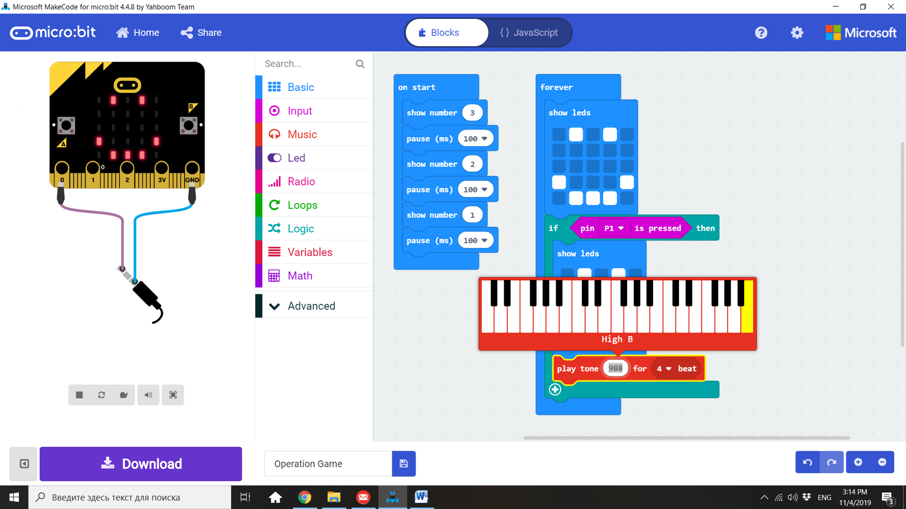
First, we will start our program with a countdown. Inside the “on start” block, we will insert a “show number” block to show the number 3. Then, we will add a “pause (ms) 100” block. Repeat two times the same formula, this time with the number 2 and 1 in the “show number” block.
From the “Basic” group we will bring the “show leds’” block and place it inside the “show leds” block. We will click on the necessary squares to create a happy face. This will be the normal state of our device.
We will bring from the “if true then” block from the “Logic” group. In the condition to be fulfilled to become true, we will insert “pin P1 is pressed” from the “Input” group.
Inside the “if… then” block, place a “show leds” block from basics. This time, create a sad face. This means that, when the wire connected to P1 touches the operation table connected to GND, the first output will be a sad face on the display.
From the “Music” group of blocks, bring the “play tone Middle C for 1 beat” block. Click the “Middle C” slot to deploy the piano. Select “High B” and change it to 4 beat (duration of the musical note.)
Finally, bring the “start melody ‘dadadum’ repeating once” block from the “Music” group. Change melody to “Funereal” and repeating to “once in background”. Then, bring the “show string” block from “Basics”, and write “GAME OVER” instead of “Hello!”
Press the “Download” button to download your code as a .hex file. When you download the code, it gets compiled from Javascript into ones and zeros that the Micro:bit can store and execute. You can find the code in the “download” folder of your computer. Drag the downloaded code over to your Micro:bit, just like dragging and dropping a file to an external drive or USB stick. You should see a yellow LED flashing next to your USB. This means the code is being transferred. When the LED finishes flashing, the program is fully downloaded.
Step 31: The Patient


Using mounting tape, stick the speaker cone to the operation table.
Draw a “patient” for the operation table. Insert a small plastic piece on each one of the three holes and test your game. If it doesn’t work, check that the wires are connected to the right pins and that the metal part of the black jumper wire is really touching the aluminum foil. Challenge your students to try to take out the three plastic objects without touching the borders.
At the end of the lesson, students must return to the teacher the Micro:bit, the Mini Speaker, the cables, the battery holder and the batteries. In addition, it is recommendable to keep the speaker cone, for future projects.

Participated in the
After School Challenge


