

Introduction: HD Engine With Arduino


Today, we are going to perform an assembly with the HD engine, which I consider to be an engineering masterpiece. We're going to pick up an HD, that is, a hard drive, disassemble this device and take out the engine. In this specific case, I dismounted an old HD, which was broken. It had about 40 gb and was used for about fifteen years, but the engine is still perfect.
I consider this HD engine to be very special. It fits into the BLDC (Brush-Less Direct Current) type, meaning it has no brushes.
In this project, we will use an Arduino Uno to control the HD Engine, using an extremely simple program that we will make in this project.
Therefore, our goal today is to create a program to control the speed of rotation of the motor that we removed from a hard drive. We use: 1 Arduino UNO, 1 brushless HD motor, 3 Tip122 Transistors, 3 1200Ω resistors, 3 1N4007 diodes, and a 12v / 5v power supply.
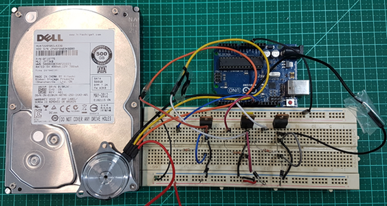
Here, we have our assembly: a protoboard with the 3 transistors. The 3 diodes are plugged into the three ports of the Arduino as Digital Out. The 5 volts that come from my computer’s USB provide the power. I’m also feeding the transistors, which in turn are feeding the three coils of the motor. I then use voltage on the coils, and this current will be shown. You will see that this engine will spend about 1A.
Step 1: Motor
I want to explain one thing: HD motor is a motor that doesn’t have torque. What is the function of the HD engine? It has a dish on top that keeps spinning, and it has to spin this disc with extremely fast precision, because otherwise it won’t read the data correctly. I find it impressive that the HD engine is made to spin trillions of turns without giving a defect.
Step 2: Arduino Uno

As always, I show here the datasheet of the component. In this case, it’s the Arduino Uno.
Step 3: TIP122

Here is the pinning. A TIP transistor always has the base, the emitter, and the collector. There are only three pins.
Step 4: 1N4007

This is the diode, for those who don’t know the electronic component. This is where the drum is the Cathode, which is the negative. Anode is the positive.
Step 5: Resistor 1k2 Ω

Each colored resistor stripe means a number.
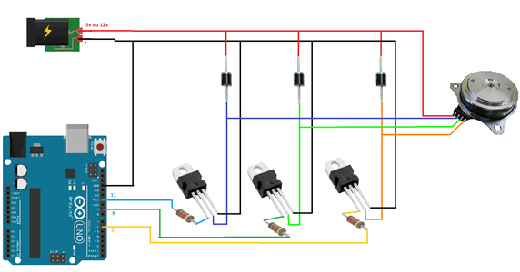
Step 6: Electric Scheme

Today I'm leaving the wiring. For those who like Arduino, I advise learning to read and write that way too. I advise why the best strategy is to not always just look at the protoboard in order to understand the circuit.
Step 7: Assembly
For those who prefer the protoboard, here's the assembly. I have the image of my engine, which has a good digital speed control.
Step 8: Example 1
What is the objective in Example 1? Using power of 5 volts, we are going to make a program that reaches the maximum speed of the engine, which is 5,400 rpm.
Source code
I have #define A, B, and C, which are those 3 reels. Each one I use on a pin. Detail: If you change A to C, the motor turns to the opposite side. You can do this by software or even by hand compiling.
The range is 6,000. Here, I’m using microsecond delay. So, it's 6 milliseconds, which is a very short time. The decrease is 15 microseconds.
In the next part, I created a table with the variables that store the times in microseconds for the delay: Minimum Delay, Maximum Acel, and Mark 1, 2, and 3.
//definição dos pinos que cada bobina representa no arduino
#define A    6
#define B    9
#define C    11


//intervalo de delay inicial que irá decair para aumentarmos a aceleração
int intervalo = 6000;

//variável responsável por armazenar o valor que decrementaremos de nosso delay
int decremento = 15;

//variáveis que armazenam os tempo em microssegundos para o delay.
const int DELAY_MINIMO      = 450;
const int DELAY_ACEL_MAXIMA = 1200;
const int DELAY_MARCO_UM    = 4500;
const int DELAY_MARCO_DOIS  = 3200;
const int DELAY_MARCO_TRES  = 2200;
Setup
In the setup () function, we will only configure the pins we will use to control the coils and the indication of LED as OUTPUT.
void setup()
{
  pinMode(A, OUTPUT);
  pinMode(B, OUTPUT);
  pinMode(C, OUTPUT);

  pinMode(LED_BUILTIN, OUTPUT);
  digitalWrite(LED_BUILTIN, LOW);//apaga o LED L
}
Loop
In the loop () function, we will make calls to control the coils, and then set the throttle to increase the engine speed.
We have Pulse 1 to 6. Those who have seen my step motor class know that when you have multiple coils, you already know that using the correct energy in the correct sequence is essential.
The correct sequence is this Pulse function, which no longer works with voltage, but with digital pulse, which is the time width, which should increase in a certain sequence. If it rises too fast, the engine may stop.
In the sequence, we give the conditionals of other interval bands to control the acceleration. We still deal with the minimum allowed delay time and the lighting of a LED.
void loop()
{
 //chamada da ativação das bobinas
 pulso(1);
 pulso(2);
 pulso(3);
 pulso(4);
 pulso(5);
 pulso(6);
 //enquanto o intervalo for maior que DELAY MÁXIMO o decremento é maior que 1 unidade.
 if(intervalo > DELAY_ACEL_MAXIMA)
 {
 //outras faixas de intervalo para ir controlando a aceleração
  if(intervalo < DELAY_MARCO_UM)
 decremento = 10;
  else if(intervalo < DELAY_MARCO_DOIS)
 decremento = 5;
  else if(intervalo < DELAY_MARCO_TRES)
 decremento = 2;
}
else decremento = 1;
//tempo mínimo de delay permitido (quanto menor mais rápido o giro)
if(intervalo > DELAY_MINIMO){
  //subtrai de intervalo o valor atual de decremento
  intervalo -= decremento;
}
else {
  //acende o led L do arduino ao chegar na velocidade máxima permitida
  digitalWrite(LED_BUILTIN, HIGH);
    }
}
Pulse
Here, specifically I show the Pulse function.
void pulso(int bobina)
{

 switch(bobina)
 {
  case 1: //liga a bobina A
  digitalWrite(A,HIGH);
  break;
  case 2://liga a bobina A e B
  digitalWrite(A,HIGH);
  digitalWrite(B,HIGH);
  break;
  case 3://liga a bobina B
  digitalWrite(B,HIGH);
  break;
  case 4://liga a bobina B e C
  digitalWrite(B,HIGH);
  digitalWrite(C,HIGH);
  break;
  case 5://liga a bobina C
  digitalWrite(C,HIGH);
  break;
  case 6://liga a bobina C e A
  digitalWrite(C,HIGH);
  digitalWrite(A,HIGH);
  break;
}
//tempo que a(s) bobina(s) ficam ligadas
delayMicroseconds(intervalo);

//desliga todas as bobinas
digitalWrite(A,LOW);
digitalWrite(B,LOW);
digitalWrite(C,LOW);
delayMicroseconds(intervalo);
}
Step 9: Example 2
Now we will make some modifications in our program so that our engine turns in its Minimum power. The lowest speed that an HD engine can do is 100 rpm. With a speed less than this, it will stop. The value of the "interval" variable must be 45,000.
So, first change the value of the variable "interval" to 45,000.
//intervalo de delay inicial que irá decair conforme aceleração
int intervalo = 45000;
Next in the LOOP function, you put only the calls to the PULSE function.
void loop()
{
  //chamada da ativação das bobinas
  pulso(1);
  pulso(2);
  pulso(3);
  pulso(4);
  pulso(5);
  pulso(6);
}
Now, just compile and run. The engine will spin at its minimum power.
See below a table with the setting for the maximum and minimum values of the motor.
• Remember that HD engines are different, and the numbers listed here are valid for the model I used. The model I used was very old and from Western Digital. What I mean is that for the numbers to be equal, your engine needs to be identical to mine. Thus, it’s important to know that your assembly is correct and that the bobinas are in their correct places, and it’s important to go find the values that correspond to your motor model, with its specific electric properties. This project is just one parameter that, with all these variables, allows you to have full control over any HD engine, provided it is BLDC.


