

Introduction: Hack a Video Game Controller With an Arduino for Greater Accessibility (or Cheating)


Step 1: Open Up the Controller Housing and See Where You Can Make Connections


Every console has a different style of controller. So the exact way that you connect to the controller will depend on the system that you are working with. But in general, most buttons are wired up the same way. The button is a normally open momentary switch. One side of the switch is wired to ground. The other side of the switch is wired to a pull-up resistor and to a pin on the controller's IC chip. When the button isn't being pressed, the pull-up resistor makes the output of the switch HIGH. But when the button is pressed, the switch connects to ground and brings the output LOW. We can simulate the effect of the button being pressed by connecting an Arduino to the switch's output pin and sending a LOW signal to the controller. The controller's IC chip will register this LOW signal the same as if the button had been pressed.
So we need to find a way to connect the output pin of each switch to the Arduino. Open up the controller housing and observe how the circuit is laid out. Look for locations that are connected to the output of the button where it would be easy to solder a wire. If you are lucky, you might find unused through-hole points already on the board. But most likely you will either need make surface mount connects or make your own through-hole connection locations.
On my controller I found that there where large contacts at the output of every button. This was most likely used to compliance testing in the factory. I thought that these would make good points to make connections. To make it easier to connect to these points, I drilled holes in each one to turn them into through-hole connectors. This also made the solder joints more secure.
Step 2: Connect Wires to Each Switch


Go through your collection of old computer cables and find a matching pair of connector cables. Be sure to select cables that have enough wires (one for every button and one for ground).One of them will be connected to the buttons on the controller. The other will be connected to the arduino. The advantage of using two cables is that you can make it easy to detach the arduino from the controller so that you don't have to have a bunch of wires always sticking out of the controller.
Start by cutting one cable so that there is about three inches of wire coming out of the header block. Separate and strip the ends of the wires. Then solder one wire to the output side of each button and one wire to the ground line for the controller.
Step 3: Cut a Slot in the Housing and Mount the Wire Connectors


Using a knife or Dremel tool, cut a slot in the housing that is just big enough for the connectors on the end of the cable. Then apply glue to three sides of the connector. Position the connector in the slot that you just cut and clamp it in place until the glue dries. Once the glue has fully cured, close up the housing. Be sure to keep track of which connectors and wires are connected to which buttons.
Step 4: Connect the Second Cable to the First Cable at the Controller

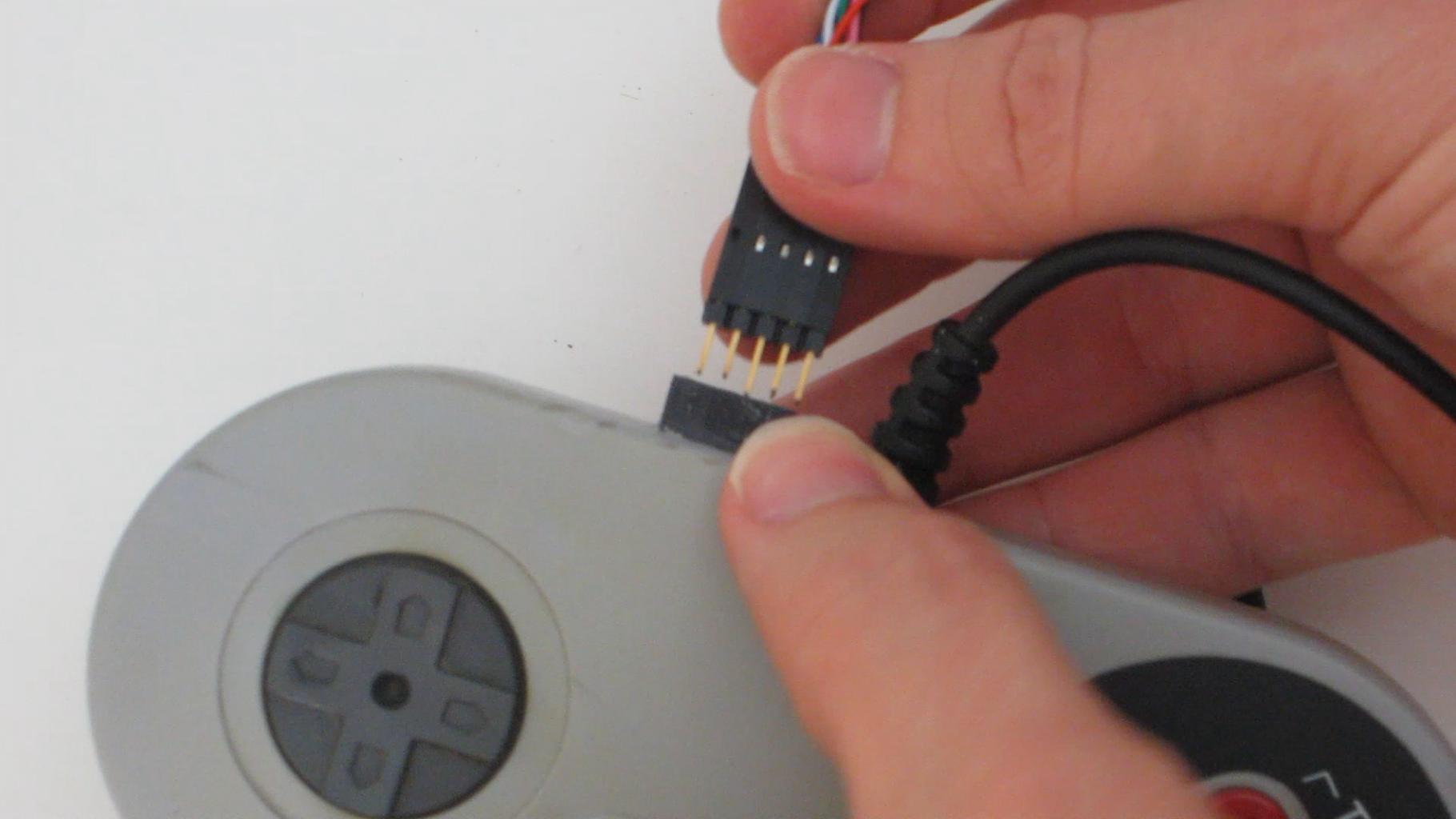

Take the second cable and match up the connector on one end with the connector that is glued into the wall of the housing.of the controller. Then connect the two cables. If you have two female cables, you may need to add a M-M coupler such as a header block.
Step 5: Attach the Wires of the Second Cable to the Arduino


We need to connect the wires from each button to the digital pins of the Arduino and connect the ground line from the controller to the ground on the Arduino. It is possible to run the button wires directly to the Arduino. However, this can cause a problem. Pressing a button on the controller while the Arduino is setting the output to HIGH would be effectively shorting the Adruino's output to ground. This can be very bad for the Arduino.
To avoid this problem, you can simply add a small diode between each button and the digital pins of the Arduino. This will allow the Adruino to still activate the controller by outputting a LOW signal, but prevent the buttons from shorting the output of the Arduino when the output signal is HIGH.
So I added a small diode to each of the button wires and insulated them with heat-shrink tubing. Then I inserted the free end of the diodes into digital pins 0-7 on the Adruino. Then I inserted the ground wire directly into one of the ground pins on the Arduino (no diode is needed for the ground line).
Step 6: Add an Activation Button


To add a button that will activate the combo sequence, select an unused digital pin. This will be an input pin that will detect the status of the activation button. You have several options as to how to wire the button to the pin. The simplest method is to wire one side of the button to this pin and wire the other side of the button to the positive voltage supply. Then use a 1 kohm resistor to connect the input pin to ground. This will act as a pull-down resistor. You could also wire the button to ground and use a pull-up resistor connected to 5V. Another alternative is to use digital pins in output mode set to LOW in place of ground and HIGH in place of the 5V PIN.
Step 7: Write and Upload Test Code
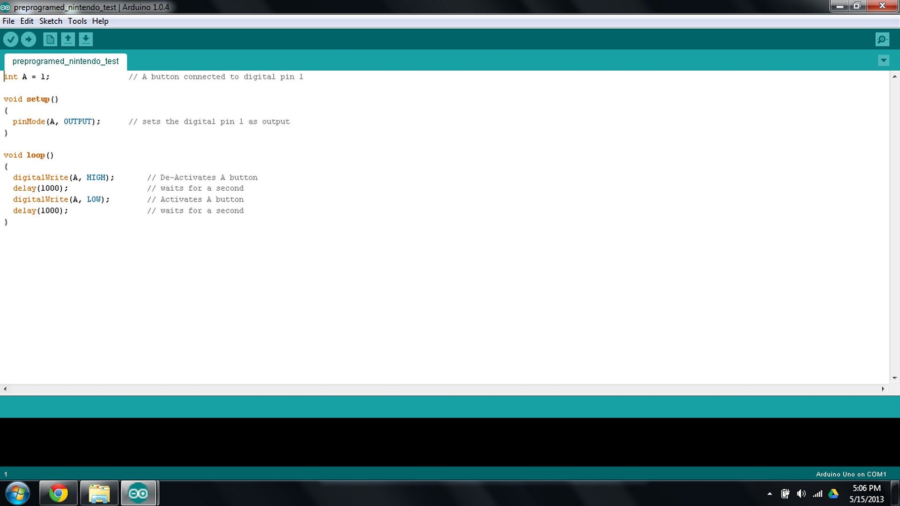
Write a simple code to test out each of the buttons to make sure that they work. Here is a simple example.
int A = 0; // A button connected to digital pin 0
int B = 1; // B button connected to digital pin 1
int Select = 2; // Select button connected to digital pin 2
int Start = 3; // Start button connected to digital pin 3
int Left = 4; // Left button connected to digital pin 4
int Right = 5; // Right button connected to digital pin 5
int Up = 6; // Up button connected to digital pin 6
int Down = 7; // Down button connected to digital pin 7
int Button = 10; // Activation button connected to digital pin 10
int ButtonHigh = 9; // High for Activation button Pull-up resistor connected to digital pin 9
void setup()
{
pinMode(A, OUTPUT); // sets the digital pin 0 as output
pinMode(B, OUTPUT); // sets the digital pin 1 as output
pinMode(Select, OUTPUT); // sets the digital pin 2 as output
pinMode(Start, OUTPUT); // sets the digital pin 3 as output
pinMode(Left, OUTPUT); // sets the digital pin 4 as output
pinMode(Right, OUTPUT); // sets the digital pin 5 as output
pinMode(Up, OUTPUT); // sets the digital pin 6 as output
pinMode(Down, OUTPUT); // sets the digital pin 7 as output
pinMode(Button, INPUT); // sets the digital pin 10 as input
pinMode(ButtonHigh, OUTPUT); // sets the digital pin 9 as output
}
void loop()
{
digitalWrite(A, HIGH); // De-Activates A button
digitalWrite(B, HIGH); // De-Activates B button
digitalWrite(Select, HIGH); // De-Activates Select button
digitalWrite(Start, HIGH); // De-Activates Start button
digitalWrite(Left, HIGH); // De-Activates Left button
digitalWrite(Right, HIGH); // De-Activates Right button
digitalWrite(Up, HIGH); // De-Activates Up button
digitalWrite(Down, HIGH); // De-Activates Down button
digitalWrite(ButtonHigh, HIGH); // Sets reference HIGH
if (Button == HIGH)
{
digitalWrite(Up, LOW); // Activates Up button
delay(100); // waits for 0.1 second
digitalWrite(Up, HIGH); // De-Activates UP button
delay(100); // waits for 0.1 second
digitalWrite(Up, LOW); // Activates Up button
delay(100); // waits for 0.1 second
digitalWrite(Up, HIGH); // De-Activates Up button
delay(100); // waits for 0.1 second
digitalWrite(Down, LOW); // Activates Down button
delay(100); // waits for 0.1 second
digitalWrite(Down, HIGH); // De-Activates Down button
delay(100); // waits for 0.1 second
digitalWrite(Down, LOW); // Activates Down button
delay(100); // waits for 0.1 second
digitalWrite(Down, HIGH); // De-Activates Down button
delay(100); // waits for 0.1 second
digitalWrite(Left, LOW); // Activates Left button
delay(100); // waits for 0.1 second
digitalWrite(Left, HIGH); // De-Activates Left button
delay(100); // waits for 0.1 second
digitalWrite(Right, LOW); // Activates Right button
delay(100); // waits for 0.1 second
digitalWrite(Right, HIGH); // De-Activates Right button
delay(100); // waits for 0.1 second
digitalWrite(B, LOW); // Activates Right button
delay(100); // waits for 0.1 second
digitalWrite(B, HIGH); // De-Activates Right button
delay(100); // waits for 0.1 second
digitalWrite(A, LOW); // Activates Right button
delay(100); // waits for 0.1 second
digitalWrite(A, HIGH); // De-Activates Right button
delay(1000); // waits for 1 second
// Now you have 999 lives
}
}
Step 8: Try Out Your Modded Controller

Connect the controller to the console and put in your favorite game. Then press the activation button. If all went well, the character should go through the pre-programmed commands. As a test, I programmed mine to play a level of Mario 2.
Step 9: Make an Accessibility Controller
To use this hack to make an accessibility controller you need to customize it to the person who will use it. So work with them and find out what their mobility range is and how they can most easily activate a button. This could be foot pedals, a mouth piece or just extra large buttons. Here is a website that offers a lot of different accessibility switches: http://www.liberator.co.uk/products/switches/switches?p=1
You can set up as many different combo buttons as you have digital pins that you can use for input. The command combos can be as short or as long as you want to program.
This is a relatively simple hack that could make a big difference to a lot of people.

Participated in the
Arduino Contest


