

Introduction: Heart Rate Monitor


This Instructable is about making a heart rate monitor using a piezoelectric sensor. I have read somewhere in the Medical Hacks section of "Hackaday Blog" and thought to give it a try. Also I've added a Processing sketch that draws a graph of the current heart rate readings. So let's get started.
Step 1: Things You Need..

1. Piezoelectric Sensor ( I removed the piezo sensor from an old buzzer that I have and used it, the removed part is shown in the picture)
2. Processing IDE
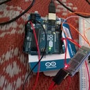
3. Arduino Board ( to read the values from the sensor)
Step 2: Getting Started...

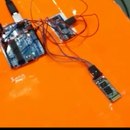
Just plug in the analog output of the sensor to any analog pins on the board (I've used A0) and connect the 5V and GND lines of the sensor. I got my piezo sensor from the buzzer that I have(broke the casing of the buzzer). and hooked it to my board as mentioned in the above lines. Now write the code in the Arduino IDE to read the analog values coming from the A0 pin and send the data to the serial port. I have attached the .ino file for your reference.
After you have flashed the code to the board, open the serial monitor and check for the readings. Initially when no pressure is applied on the piezo sensor, the readings shown on the monitor are zero. When you gently press the piezo sensor to one of your fingertips, it starts showing some values. these values correspond to the vibrations produced by your pulse. When I've tried I got a noise free and normal heart beat(72bpm). I don't know whether these are the accurate values, because I don't have any device to measure my heart rate. So I've done some pushups and checked my pulse again surprisingly it showed (82-85bpm). Hence I think the values read from the sensor might be, if not accurate, but atleast approximate values.
Attachments

Step 3: Displaying Sensor Values...

The values that are read from the sensor in the previous step are now redirected to the serial port of the processing monitor. In order to do this, make changes in the following step.
myPort = new Serial(this, "COM3", 9600);
Here COM3 is the serial port where the values are being sent by Arduino. You may have to change it to your port number probably. You can find that in Tools-->port inside Arduino IDE. After modifying the sketch, run it. Make sure that you have closed the serial monitor of the arduino before you do this, because both sketches will try to listen at the same port and this may cause the processing sketch to fail. Now you can see the live graph being plotted by the sketch.
Try to understand the code, and make a few tweaks and changes( or write your own sketch) to make it look more similar like a real time heart rate monitor


