

Introduction: Industrial IoT Controller With Raspberry Pi


Hello, last year a client installed security bollards at the access points to their industrial facilities and asked me to design an electronic system to control bollards via TCP / IP from a control tower.
This INSTRUCTABLE describes the process I followed, from the preliminary idea, through a prototype, to the final version delivered to the client.
The design of equipment for industrial use requires careful preparation and must be constructed according to materials and components approved for industrial use.
In this INSTRUCTABLE I focus on the points that make the difference between making a prototype and making a product with commercial or industrial quality.
Although from the technical point of view the solution of the problem is reduced to controlling a pair of relays and we can find in the market a myriad of these products ready to be installed. Making a customized product and customer needs is a slightly more complex process.
For me, the difference that marked the quality between a prototype and a commercial version was the design of the Graphical User Interface and is a part that I will cover extensively in this INSTRUCTABLE.
The ideas shown here can be modified and adapted to any electromechanical device that can be controlled with a relay: water pumps, garage doors, shutters, electric doors, etc.
IMPORTANT: English is not my first language and the original project of this INSTRUCTABLE was made in Spanish. Although almost all the information was passed to English for this INSTRUCTABLE, the test videos and some photographs will be in Spanish.
If you have a suggestion to improve it, please let me know.
Let us begin.
Step 1: BACKGROUND

From Reliance Foundry Site:
"A bollard is a short post used to create a protective or architectural perimeter. When installed primarily as a visual guide, bollards guide traffic and mark boundaries. They come in a wide variety of shapes and styles to accentuate or visually stand out in their settings. Bollards can also be constructed to physically block vehicle incursion, protecting people and property. These security bollards may have decorative elements or be chosen to complement the landscape, but their primary consideration is resistance to impact forces. Bollards can be made from almost any material, depending on their needed function, but the most common bollards are metal, stone, cement, or plastic."
And for BLOCKAIDES Site:
"Automatic Bollards"
"This type of bollard is also known as a rising or telescopic bollard. These are retractable bollards that can rise out of the ground to block traffic or withdraw back into the ground to allow traffic to pass. With most able to extend to their full height in a matter of seconds, they’re an efficient, flexible way to manage traffic and keep pedestrians safe. Automatic bollards can be controlled pneumatically, hydraulically, or electrically. This selection is often dependent on site-specific applications and uses. These bollards are constructed out of carbon steel or stainless steel and are usually available in a variety of different finishes. Automatic bollards are permanently installed below grade and require regular maintenance. Primary Uses for Automatic Bollards These are ideal for situations where the flow of traffic will be varying, and entry and exit might change at a moment’s notice. One example of a practical application for automatic bollards might be a parking garage or parking lot. They’re also perfect for use at the entrance to museums, zoos or other public facilities where admittance is restricted after a certain hour."
Step 2: CLIENT INTERVIEW


After researching all about bollards, I asked for a first interview with the client to gather the information that would allow me to know the client's needs.
Before arriving at the interview with the client, prepare a brief technical sheet with the idea of the project, so that the client had an idea of the product he was going to receive.
After the next step was to ask the client for the following information:
- Brand and model of Bollards
- Copy of the Bollards Installation Manual.
- How many were going to be installed.
- Where they were going to install.
- How and who controls the entry and exit of the facilities.
- Identification or name assigned to the facilities and equipment.
- What are the requirements of the required control system?
- System delivery time
Attachments

Step 3: ANALYSIS OF CLIENT INFORMATION - (WHAT)

The client provided me with the brand and model of the Bollard to be installed, as well as its manual.
The customer model is an Access PRO Bollard XB220H06K with a hydraulic drive. The bollard has a control box that handles the hydraulic pump and a piston that performs the movement up and down. The piston has two limit switches placed one in the fully retracted position and the other in the fully removed position to indicate its position to the control system. It has two connections to place a manually operated keypad. After reading the manual, the connection points for the manual keypads were identified as well as identifying the limit switch in the retracted position.
Attachments
Step 4: ANALYSIS OF CLIENT INFORMATION - (WHERE)

7 bollards were going to be installed in two access control zones at the customer's premises. The main access control (ACCESS AREA “A”) consists of two vehicular communication routes: One of entry and one of exit each of three access lanes. In this area, 4 bollards were to be installed: 2 in the entrance area and 2 in the exit zone.
The second access control (ACCESS AREA “B”) consists of 3 single-lane communication routes: One entryway, one exit way, and one bidirectional way. In this area, 3 bollards were to be installed.
The distance between the access control booths is one kilometer.
With this data, the process of assigning an ID to each bollard was carried out. This identification was made by the client:
ACCESS AREA "A"
INPUT AREA:
- BOLLARD 1 ID: CAS01-B01-EA
- BOLLARD 2 ID: CAS01-B02-ET
OUTPUT AREA:
- BOLLARD 3 ID: CAS01-B03-ST
- BOLLARD 4 ID: CAS01-B04-SA
ACCESS AREA “B”
INPUT AREA:
- BOLLARD 5 ID: CAS02-B01-SA
OUTPUT AREA:
- BOLLARD 6 ID: CAS02-B02-ST
BIDIRECCONAL AREA:
- BOLLARD 7 ID: CAS02-B03-E/S-AT
Step 5: ANALYSIS OF CLIENT INFORMATION - SPECIFIC REQUIREMENTS
The client requires a control system for their bollards that operates through an ethernet communication network, using TCP / IP communication protocols, the control system must have a manual keypad to be able to operate the system locally in case of a control system or communication network failure. The graphical user interface (GUI) must be friendly and easy to use and must be able to monitor the status of each bollard, as well as indicate the temperature, available memory and the status of the control system supplied.
The control system must have a touch screen to be able to operate the system locally.
The equipment will be placed inside the access booths.
The time to carry out the project is 40 days.
In order to place a Purchase Order, the customer needs to evaluate a prototype.
Step 6: THE IDEA

With the customer data already analyzed, the next step was the choice of a microcontroller capable of performing all the required tasks efficiently and in a fast and elegant way. I chose to use a Raspberry Pi 3B+ because I had previously made a mobile robot using this microcontroller programmed with NODE RED. So the next step was to determine the system architecture. A single Raspberry to control All Bollards or One for each Bollard. I decided to use an intermediate point, to design a control box for every 3 bollards.
With these considerations, the base design was as follows:
A Raspberry Pi with a 3.5 ”LCD touch screen, an 8-Channel 5V Relay Module, a 5 VDC power supply and terminal blocks for making electrical connections, all placed in an ABS plastic enclosure with IP65 protection.
With the basic idea established, it was time to plan the following steps:
- ACQUISITION OF MATERIALS
- SOFTWARE INSTALLATION IN THE RASPBERRY
- WRITING THE BOLLARD CONTROL PROGRAM
- CONSTRUCTION OF A PROTOTYPE FOR THE CLIENT EVALUATION
Step 7: PARTS & TOOLS FOR THE PROTOTYPE

PARTS:
- Raspberry Pi 3B+
- Raspberry LCD Touch 3.5"
- 8-Channel 5V Relay Module
- 5 VCD / 3 AMP wall plug power supply
- DIN-Rail
- Terminal Blocks (Weidmuller 1020100000 WDU 4)
- Surface type duplex PLUG EG78V
- ABS NEMA IP66 enclosure
- Cable AWG 14
TOOLS:
- Soldering Iron
- Screwdrivers
Step 8: SOFTWARE: RASPBIAN INSTALLATION


In this section I should show you how to install the operating system for the Raspberry Pi, however, I don't know if you are already an expert driving the Raspberry Pi or it is your first time.
If you are an expert this section does not interest you and you should go directly to the design of the GUI, but if you are a beginner then better than go hand in hand with the experts, so I recommend you download the magazine "The Official Raspberry Pi Beginner's Guide".
In Annex "A" of the magazine comes how to install the operating system in micro SD memory.
Step 9: SOFTWARE: NODE RED INSTALLATION

From Node-Red.org:
Node-RED is a programming tool for wiring together hardware devices, APIs and online services in new and interesting ways.
It provides a browser-based editor that makes it easy to wire together flows using the wide range of nodes in the palette that can be deployed to its runtime in a single-click.
Node-RED provides a browser-based flow editor that makes it easy to wire together flows using the wide range of nodes in the palette. Flows can be then deployed to the runtime in a single-click.
JavaScript functions can be created within the editor using a rich text editor. A built-in library allows you to save useful functions, templates or flows for re-use.
To install Node-Red in Raspberry Pi, follow these instructions.
To getting started with Node-RED in Raspberry Pi, follow this link.
It is important to understand how messages work in NODE RED. To learn more about this topic, follow this link and this one.
NODE RED INSTALLATION:
We want Node-RED to run when the Pi is turned on, or re-booted. To enable the service to autostart by running the command:
sudo systemctl enable nodered.service
And for the program to run in the browser when the Raspberry Pi is turned on, type in the terminal:
$ sudo nano .bashrc
and add the following to the end of the file:
chromium-browser —kiosk 127.0.0.1:1880/ui/#!/1
Step 10: FRED: Font Red for Node Red

We have finished installing Raspberry and Node-Red.
We could continue working on the Raspberry but there are important reasons to continue with the development of the program on an external computer and once the program is ready and debugged, then we can migrate it to the Raspberry. Among the reasons for using an independent development computer are:
1.- It is a commercial product that we are developing so we want the Raspberry to have only the client program code and nothing else.
2.- During the development of the program we usually download a lot of extra software to be able to develop the program and test the code and we do not want these programs to be in the Client's Raspberry,
3.- During the development stage we make many online queries and we do not want to have all this data flow, cookies, downloads, etc., in the Raspberry.
The tool I use to develop in Node-Red is FRED.
If you don’t already have an account on FRED (Cloud Node-RED), set one up now. It’s free for a demo account, which can be used for these tutorials and any other experiments you may have with Node-RED. Register for a free account at http://fred.sensetecnic.com.
After registering, make sure to activate your account via your email. You will not be able to log in until you validate your account.
Although it does not have the GPIO components of Raspberry Pi, these can be simulated: A rpi-gpio in node can be simulated with an inject input node and a rpi-gpio out node can be simulated with a debug output node.
However, it is not necessary to have FRED installed and you can continue working on Node-Red of the Raspberry Pi.
Step 11: SOFTWARE: GRAPHICAL USER INTERFACE (GUI)


Well, we already have the Operating System and NODE RED programming software installed, now we can start writing the lines of code that will make up the program, but what is the idea? Where do we start? Although from the hardware point of view the system is very simple: A raspberry controlling relays, the longest and most complicated part of the project was the graphic interface design.
The easiest way to control bollards via TCP/IP was to use the NODE RED switch components, however, this was not the professional and commercial way to deliver the GUI design. I decided to do the graphic control in the most real way possible, so that the image of a bollard that could be animated was designed, simulating the rise and fall of it, also indicating in color the status of the bollard:
RED
when it was rising or in fully extended position and
GREEN
when the bollard was fully retracted. The animation is activated through two buttons placed at the top and bottom of the interface. The upper buttons are red and with the legend "UP" and the lower buttons are green and with the legend "DOWN". I used a TEMPLATE node of NODE RED in which the source code of the program in CSS and HTML was embedded. To better understand this part of the code, let's look at its three main sections: "style"(CSS), "body" and "script".
Step 12: GUI - "style" Section

CSS is a language that describes the style of an HTML document.
CSS describes how HTML elements should be displayed.
CSS can be added to HTML elements in 3 ways:
- Inline - by using the style attribute in HTML elements
- Internal - by using a "style" element in the "head" section.
- External - by using an external CSS file.
We will use the Internal Way:
<html>
<style>

....some code

</style>
Check this CSS Tutorial where you will find complete CSS references of all properties and selectors with syntax, examples, browser support, and more.
Check this tutorial to How to understand CSS Position Absolute once and for all.
To get a better idea of the figures that we can define in the style section see the following link.
ANALYZING COMPONENTS
Look carefully at the figure, the components that form the graphic interface were drawn and then I will detail the code for each of them.
To define the green button (DOWN BUTTON), we use the following code:
.buttonGreen_B1 {
  background-color: #4CAF50; /* Green */
  border: none;
  color: white;
  padding: 15px 32px;
  text-align: center;
  text-decoration: none;
  display: inline-block;
  font-size: 16px;
  margin: 4px 2px;
  cursor: pointer;
}
To define the red button (UP BUTTON), we use the following code:
.buttonRed_B1 {
  background-color: #f44336;
} /* Red */
To define the main rectangle that contains all the elements, we use the following code:
#container_B1 {
  top: 0px;
  left: 0px;
  width: 120px;
  height: 460px;
  position: relative;
  background-color: #333333;
}
To define the shape of the bollard we use three rectangles (# r1_B1, # r2_B1 and # r3_B1).
To define rectangle # r1_B1, we use the following code:
#r1_B1 {
    display: inline-block;
    top: 10px;
    left: 25px;
    width: 72px;
    height: 10px;
    position: absolute;
    border: 1px solid black;
    background-color: #f44336;
}
To define rectangle # r2_B1, we use the following code:
#r2_B1 {
    top: 10px;
    left: 2px;
    width: 66px;
    height: 10px;
    position: absolute;
    border: 1px solid black;
     background-color: #aaaa44;
}
To define rectangle # r3_B1, we use the following code:
#r3_B1 {
    display: inline-block;
    top: 10px;
    left: -2px;
    width: 70px;
    height: 200px;
    position: absolute;
    border: 1px solid black;
   background-color: #f44336 ;
}
To simulate the LED lights of the bollard we use six dots (#dot1_B1 to #dot6_B1),
I use the following code:
#dot1_B1 {
  display: inline-block;
  top: 2px;
  left:  5px;
  height: 3px;
  width: 3px;
  position: absolute;
  border-radius:100%;
  border: 2px solid yellow;
  background-color: #ff0000;
}

#dot2_B1 {
  display: inline-block;
  top: 2px;
  left:  15px;
  height: 3px;
  width: 3px;
  position: absolute;
  border-radius:100%;
  border: 2px solid yellow;
  background-color: #ff0000;
}

#dot3_B1 {
  display: inline-block;
  top: 2px;
  left:  25px;
  height: 3px;
  width: 3px;
  position: absolute;
  border-radius:100%;
  border: 2px solid yellow;
  background-color: #ff0000;
}


#dot4_B1 {
  display: inline-block;
  top: 2px;
  left:  35px;
  height: 3px;
  width: 3px;
  position: absolute;
  border-radius:100%;
  border: 2px solid yellow;
  background-color: #ff0000;
}

#dot5_B1 {
  display: inline-block;
  top: 2px;
  left:  45px;
  height: 3px;
  width: 3px;
  position: absolute;
  border-radius:100%;
  border: 2px solid yellow;
  background-color: #ff0000;
}


#dot6_B1 {
  display: inline-block;
  top: 2px;
  left:  55px;
  height: 3px;
  width: 3px;
  position: absolute;
  border-radius:100%;
  border: 2px solid yellow;
  background-color: #ff0000;
}
To define the bollard housing we use two rectangles (# r4_B1 and # r5_B1).
To define rectangle # r4_B1, we use the following code:
#r4_B1 {
    top: 214px;
    left: 5px;
    width: 110px;
    height: 10px;
    position: absolute;
    border: 1px solid black;
    background-color: #666666;
}
To define rectangle # r5_B1, we use the following code:
#r5_B1 {
    display: inline-block;
    top: 225px;
    left: 22px;
    width: 82px;
    height: 218px;
    position: absolute;
    border: 1px solid black;
    background-color: #443333;
   }
We have finished writing the CSS section, let's now go to the body section...
Step 13: GUI - "body" Section

The body section contains three important parts:
1.- The definition of the UP and DOWN buttons.
The UP button has the following source code:
<button class="buttonGreen_B3 buttonRed_B3" onclick="myMoveUp_B3()" ng-click="send({payload: 2})”>__UP__</button> The DOWN button has the following source code:
<button class="buttonGreen_B3" onclick="myMoveDown_B3()" ng-click="send({payload: 1})">DOWN</button> 2.-The div tag defines a division or a section in an HTML document.
The div element is often used as a container for other HTML elements to style them with CSS or to perform certain tasks with JavaScript.
This tag is then used to contain all the elements of the Bollard:
   <div id="container_B3">
    	<div id=r4_B3></div>
  	<div id=r5_B3></div>
	<div id="r1_B1">
	    <div id="r2_B1">
		<div style="text-align:center">
	  		<div id="dot1_B1"></div>
  			<div id="dot2_B1"></div>
  			<div id="dot3_B1"></div>
  			<div id="dot4_B1"></div>
	  		<div id="dot5_B1"></div>
  			<div id="dot6_B1"></div>
		</div>
		<div id=“r3_B1"></div>
	    </div>
	 </div>
   </div>
3.- The script section, which we will see in the next step.
Step 14: GUI - "script" Section

The section has three important functions: the function(scope) that is responsible for obtaining external input values (GPIO IN):
<script>
(function(scope) {scope.$watch('msg.payload', function(newValue1,oldValue1) {
            console.log('BOLLARD 1');
            console.dir(newValue1);
            if (newValue1===oldValue1) {
             dos1(oldValue1);
            } else {
             uno1(newValue1);
            }
                });
    })(scope);
    function uno1(bale1){
        if (bale1 == true){
      console.dir('TRUE b1:'+bale1);
      myMoveUp_B1();
        } else
        {
            console.dir('FALSE b1:'+bale1);
            myMoveDown_B1();
      }
    }
    function dos1(gale1){
      console.dir('DOS b1:'+gale1);
    }
The function myMoveDown_B1(), to move DOWN the Bollards:
var altura_B1 = 0;
function myMoveDown_B1() {
  var elem = document.getElementById("r1_B1");
  var pos = 0;
  var id = setInterval(frame, 5);
  function frame() {
    if (altura_B1 >= 214) {
      clearInterval(id);
      elem.style.backgroundColor = "#4CAF50";
      var elem1 = document.getElementById("r1_B1");
      elem1.style.backgroundColor = "#4CAF50";
    } else {
      altura_B1++;
      elem.style.top = altura_B1 + 'px';
      elem.style.left = 10;
      elem.style.backgroundColor = "#f44116";
    }
  }
}
And the function myMoveUp_B1(), to move UP the Bollards:
function myMoveUp_B1() {
   var elem1 = document.getElementById("r1_B1");
      elem1.style.backgroundColor = "#f44116";
  var elem = document.getElementById("r1_B1");
  var pos = 220;
  var id = setInterval(frame, 5);
  function frame() {
    if (altura_B1 == 0) {
      clearInterval(id);
    } else {
      altura_B1--;
      elem.style.top = altura_B1 + 'px';
      elem.style.left = 10;
      elem.style.backgroundColor = "#f44116";
    }
  }
}
</script>
Step 15: PUTTING IT ALL TOGETHER - THE TEMPLATE NODE


It's time to put all the code together. Within a TEMPLATE node, place the following code:
<html>
<style>
.buttonGreen_B1 {
  background-color: #4CAF50; /* Green */
  border: none;
  color: white;
  padding: 15px 12px;
  text-align: center;
  text-decoration: none;
  display: inline-block;
  font-size: 16px;
  margin: 4px 2px;
  cursor: pointer;
}
.buttonRed_B1 {
    background-color: #f44116;
} /* Red */
#container_B1 {
  top: 0px;
  left: 0px;
  width: 120px;
  height: 460px;
  position: relative;
  background-color: #111111;
}
#r1_B1 {
    display: inline-block;
    top: 10px;
    left: 25px;
    width: 72px;
    height: 10px;
    position: absolute;
    border: 1px solid black;
    background-color: #f44116;
}
#r2_B1 {
    top: 10px;
    left: 2px;
    width: 66px;
    height: 10px;
    position: absolute;
    border: 1px solid black;
     background-color: #222222;
}
#r3_B1 {
    display: inline-block;
    top: 10px;
    left: -2px;
    width: 70px;
    height: 200px;
    position: absolute;
    border: 1px solid black;
   background-color: #f44116
}
#r4_B1 {
    top: 214px;
    left: 5px;
    width: 110px;
    height: 10px;
    position: absolute;
    border: 1px solid black;
    background-color: #666666;
}
#r5_B1 {
    display: inline-block;
    top: 225px;
    left: 22px;
    width: 82px;
    height: 218px;
    position: absolute;
    border: 1px solid black;
    background-color: #441111;
 }
#dot1_B1 {
  display: inline-block;
  top: 2px;
  left:  5px;
  height: 1px;
  width: 1px;
  position: absolute;
  border-radius:100%;
  border: 2px solid yellow;
  background-color: #ff0000;
}
#dot2_B1 {
  display: inline-block;
  top: 2px;
  left:  15px;
  height: 1px;
  width: 1px;
  position: absolute;
  border-radius:100%;
  border: 2px solid yellow;
  background-color: #ff0000;
}
#dot3_B1 {
  display: inline-block;
  top: 2px;
  left:  25px;
  height: 1px;
  width: 1px;
  position: absolute;
  border-radius:100%;
  border: 2px solid yellow;
  background-color: #ff0000;
}
#dot4_B1 {
  display: inline-block;
  top: 2px;
  left:  15px;
  height: 1px;
  width: 1px;
  position: absolute;
  border-radius:100%;
  border: 2px solid yellow;
  background-color: #ff0000;
}
#dot5_B1 {
  display: inline-block;
  top: 2px;
  left:  45px;
  height: 1px;
  width: 1px;
  position: absolute;
  border-radius:100%;
  border: 2px solid yellow;
  background-color: #ff0000;
}
#dot6_B1 {
  display: inline-block;
  top: 2px;
  left:  55px;
  height: 1px;
  width: 1px;
  position: absolute;
  border-radius:100%;
  border: 2px solid yellow;
  background-color: #ff0000;
}
</style>
<body>
<p>
<button class="buttonGreen_B1 buttonRed_B1" onclick="myMoveUp_B1()" ng-click="send({payload: 2})">__UP__</button>
</p>
<div id="container_B1">
    <div id=r4_B1></div>
    <div id=r5_B1></div>
<div id="r1_B1">
<div id="r2_B1">
<div style="text-align:center">
  <div id="dot1_B1"></div>
  <div id="dot2_B1"></div>
  <div id="dot3_B1"></div>
  <div id="dot4_B1"></div>
  <div id="dot5_B1"></div>
  <div id="dot6_B1"></div>
</div>
<div id="r3_B1">
</div></div> </div>
</div>
<p>
<button class="buttonGreen_B1" onclick="myMoveDown_B1()" ng-click="send({payload: 1})">DOWN</button>
</p>
<script>
(function(scope) {scope.$watch('msg.payload', function(newValue1,oldValue1) {
            console.log('BOLLARD 1');
            console.dir(newValue1);
            if (newValue1===oldValue1) {
             dos1(oldValue1);
            } else {
             uno1(newValue1);
            }
       });
    })(scope);
    function uno1(bale1){
        if (bale1 == true){
      console.dir('TRUE b1:'+bale1);
      myMoveUp_B1();
        } else
        {
            console.dir('FALSE b1:'+bale1);
            myMoveDown_B1();
      }
    }
    function dos1(gale1){
      console.dir('DOS b1:'+gale1);
    }
var altura_B1 = 0;
function myMoveDown_B1() {
  var elem = document.getElementById("r1_B1");
  var pos = 0;
  var id = setInterval(frame, 5);
  function frame() {
    if (altura_B1 >= 214) {
      clearInterval(id);
      elem.style.backgroundColor = "#4CAF50";
      var elem1 = document.getElementById("r1_B1");
      elem1.style.backgroundColor = "#4CAF50";
    } else {
      altura_B1++;
      elem.style.top = altura_B1 + 'px';
      elem.style.left = 10;
      elem.style.backgroundColor = "#f44116";
    }
  }
}
function myMoveUp_B1() {
   var elem1 = document.getElementById("r1_B1");
      elem1.style.backgroundColor = "#f44116";
  var elem = document.getElementById("r1_B1");
  var pos = 220;
  var id = setInterval(frame, 5);
  function frame() {
    if (altura_B1 == 0) {
      clearInterval(id);

    } else {
      altura_B1--;
      elem.style.top = altura_B1 + 'px';
      elem.style.left = 10;
      elem.style.backgroundColor = "#f44116";
    }
  }
}
</script>
</body>
</html>
Ready, we have our full animation working. Now let's add the next two bollards.
Step 16: Adding the Two Remaining Bollards

To add the remaining two bollards, we can copy and paste the code that we have already created in another TEMPLATE node, changing only the identification of each bollard.
You can do it by following the steps below:
1.- Copy the entire code from the TEMPLATE node to your preferred text editor.
2.- In your text editor, select the search and replace option and make the following modifications:
3.- For the second Bollard change the text: _B1 to _B2.
4.- For the third Bollard change the text: _B2 to _B3.
5.- Now copy all the modified text.
6.- Insert a new TEMPLATE node and paste the text you have modified.
READY, you already have the second animated Bollard.
To add the third, repeat the previous steps.
We are done with the code of the Graphical User Interface. It's time to add the input and output nodes and some more components.
Step 17: I/O CONNECT


Since we have seen that the GUI operates according to the program, it is time to add connections with the outside world. We will place the GPIO NODES for handling Raspberry inputs and outputs from NODE RED.
To synchronize the physical state of the bollards with the GUI, it is necessary to connect an input node of the Raspberry Pi that is physically connected to the lower position limit switch of each bollard. Thus when the position limit switch is activated it indicates that the bollard is fully retracted and we have to ensure that our GUI shows the bollard in this position (Green color). As soon as the Bollard rises, this switch is no longer active and with it the Raspberry input will change and this will be reflected in the GUI (Red color).
To do all this we need three GPIO inputnodes assigned to pins:
- 29 (GPIO_25)
- 31 (GPIO_32)
- 32 (GPIO_12)
If you are using FRED, add two inject nodes for each Bollard, one set to true and the other as false.
If you are working from the Raspberry Pi, just add the rpi gpio input node.
We will improve our program.
Now we want to add to the DASHBOARD a Global Switch that handles all Bollards simultaneously. This is useful for emergencies when you want to close or open all accesses simultaneously. For this, we add a SWITCHnode of the dashboard palette and its output is connected to the inputs of each of the three TEMPLATE nodes. (Look at the image to see its settings).
Now let's work with the output section.
At the output of each TEMPLATE node, we will add a SWITCH node of the function palette and we will configure it in such a way that depending on the value of the received message, activate one of the two configured outputs:
If a “1” is received, we will send a pulse to the relay that activates the lowering of the bollard.
If a “2” is received, we will send a pulse to the relay that activates the bollard rise.
Where these numbers "1" and "2" come from. Remember when we create the buttons in the body section:
<button class="button_B3 buttonRed_B3" onclick="myMoveUp_B3()" ng-click="send({payload: 2})”>__UP__</button> And
<button class="button_B3" onclick="myMoveDown_B3()" ng-click="send({payload: 1})">DOWN</button> the ng-click = "send ({payload: 2})” and ng-click = "send ({payload: 1})” command is responsible for sending these numbers outside the node.
Remember this because later we will see it again.
To each of the outputs of the SWITCHnode, we will place a trigger node of the function palette and configure it to have a duration of 1 second and that it first sends a false pulse and then a true value. (This is because the installed relay module operates with negative values, that is, we have to apply a negative pulse to the relay input for it to be activated).
Finally, we will add the output nodes.
If you are using FRED, add a debug node to the output of each trigger node.
If you are working from the Raspberry Pi, only add the rpi gpio output node to the output of each trigger node.
To do all this we need six GPIO output nodes assigned to pins:
- 33 (GPIO_13)
- 36 (GPIO_16)
- 35 (GPIO_19)
- 38 (GPIO_20)
- 37 (GPIO_26)
- 40 (GPIO_21)
We have finished the program...for the moment.
I provide you with the complete code of what we have seen so far. Download the attached text file and follow the instructions in the video to install it in NODE RED.
Attachments

Step 18: INSTALL 3.5" LCD


So far we have been working on a large monitor. Now the program is ready so we can now install the drivers for the 3.5 ”Touch LCD screen.
The installation process of the drivers for the LCD is as follows:
Open the terminal and type:
git clone https://github.com/waveshare/LCD-show.git
cd LCD-show
sudo ./LCD-35-show
Attachments
Step 19: Links About Industrial Components
If you do not have experience in industrial electrical components it is advisable to see the following links on the installation of industrial components:
Enclosures Ratings and standards
Eaton Cutler Hammer M 22 Series Contact Blocks Wire Installation Demo
M22 Series Pushbutton Assembly & Disassembly
M22 22mm IEC Pushbuttons - Eaton
And you can also find interesting links in my book Basic Electronics: a multitouch book on electronic theory and components with a large number of figures, interactive images, photo gallery, videos on electronic technology, 3D models, PDF files of supporting documents and electronic component datasheets, links to the best websites on electronic theory and components, as well as links to videos with the most representative in cutting-edge technology.
Step 20: BUILDING THE PROTOTYPE


For the software part, everything is ready for preliminary tests, just need to physically build the prototype, for this I use a box of electrical connections ABS plastic measures 225mm x 175mm x 100mm. Inside the box was placed a DIN RAIL with terminals to make interconnections between the relays and bollards, as well as distribute the supply voltages. The 8 Relay Module, the duplex contact, the 5 VDC wall plug power supply and a support for the Raspberry Pi with its LCD Display were also placed.
Step 21: WIRING THE PROTOTYPE


For Wiring follow the diagram above.
It is necessary to have an order when internal wiring is done in electronic equipment to avoid complications when installing the cables. For the design of the prototype I use the following pattern of placement of terminal blocks:
- TERMINAL BLOCK green/yellow - limit switch
- TERMINAL BLOCK beige - limit switch & RPi GPIO 5, 6 & 12
- TERMINAL BLOCK blue - GND
- TERMINAL BLOCK beige - DOWN
- TERMINAL BLOCK beige - UP
- TERMINAL BLOCK orange - GNG
- TERMINAL BLOCK beige - Push-Button DOWN
- TERMINAL BLOCK beige - Push-Button UP
I use colored wire for easy identification.
- Black cable for common or negative connections
- Green cable relays to lower the bollard
- Blue Cable for relays to raise a Bollard
The Raspberry connection to the relay module is as follows:
- Relay Module IN8 to RPi pin 33 (GPIO_13)
- Relay Module IN7 to RPi pin 36 (GPIO_16)
- Relay Module IN6 to RPi pin 35 (GPIO_19)
- Relay Module IN5 to RPi pin 38 (GPIO_20)
- Relay Module IN4 to RPi pin 37 (GPIO_26)
- Relay Module IN3 to RPi pin 40 (GPIO_21)
Step 22: PROTOTYPE TEST


Once finished the prototype and the base code working, I went to the customer's premises to test the system and delivered an update of the product data-sheet.
To impress the client, an Ipad was used to wirelessly handle the prototype. The wireless connection was made through a cell phone and the wireless connection was enabled on the raspberry only for this test.
Both the Hardware and the Software behaved as intended. Therefore, the Client's authorization was received to proceed to the final phase of the project, which includes the creation of the control system with additional functions not included in the prototype, which are detailed in the next step.
Attachments
Step 23: PROTOTYPE VS FINAL VERSION


There are several things to do to deliver the final equipment to the client:
- The buttons must be installed to operate the Bollards in case of failure of the electronic equipment or for failures in the communications network.
- The wall plug power supply must be changed to a power supply for industrial use.
- The Terminal Blocks have to be changed to reduce the connection space and eliminate the jumpers.
- The system monitoring module and the ethernet network configuration module must be implemented.
One of the requests made by the client was that the manually operated buttons remain inside the equipment to prevent anyone without authorization from operating the bollards. Only in case of failure of the electronic equipment would the equipment be opened to allow access to these buttons.
- Finally and perhaps most importantly, it is to improve the user experience.
This led to major changes in the GUI.
Step 24: MATERIALS FINAL VERSION


PARTS:
- Raspberry Pi 3B+Raspberry
- LCD Touch 3.5"
- 8-Channel 5V Relay Module
- 5 VCD / 3 AMP power supply
- DIN-Rail
- Terminal Blocks (Weidmuller ZDU 2.4/4)
- Weidmuller DEK 5 FS
- Push-Button M22-DDL-GR
- M22-A Adapter
- Switch M22-K10
- ABB IP66 enclosure PART NUMBER: M128120020
- ABB Metal Plate PART NUMBER: M128450000
- Cable AWG 14 colors: Red, Green, and Black.
- Breadboard Jumper Wires Prototype Board Dupont Wire Female to Female
TOOLS:
- Soldering Iron
- Screwdrivers
Step 25: FINAL VERSION AT a GLANCE
Step 26: WIRING THE FINAL VERSION


To make the wiring follow the "FROM / TO" instructions in the attached document "Cable List FROM / TO".
Like the prototype, use colored wire to facilitate identification:
- Black cable for common or negative connections
- Green cable relays to lower the bollard
- Red Cable for relays to raise a Bollard
Attachments
Step 27: RELAY & TERMINAL BLOCK WIRING


To connect the 8 Relay Module to the power supply, I cut a female to female Dupont jumper wire and soldered it to an AWG 14 wire, so that it could be connected to the terminal block.
To connect the Raspberry Pi inputs to the terminal block, I cut a female to female Dupont jumper wire and soldered it to an AWG 14 wire, so that it could be connected to the terminal block.
Three resistors (1.5 kohms/1 W) were used to connect the limit switches to the raspberry pi inputs.
One of its ends was placed directly on the terminal block and the other end was welded to an AWG 14 wire connected to the 5 VDC.
Step 28: SHEET METAL SUPPORT


For the design of the support of the buttons, I first made a cardboard model to be able to visualize the location of the components in the best way and detect possible interference from both the wiring and the location of the components. Once you determine that the cardboard model was functional, design in Fusion 360 a sheet metal model and have it manufactured in 18 gauge galvanized steel sheet and finished in matt black acrylic enamel paint.
Once I received the finished designs, continue with the installation of the buttons and the Raspberry Pi.
Attachments
Step 29: Raspberry Pi & PUSH-BUTTON MOUNTING


The Raspberry Pi was mounted on an acrylic plate to avoid possible shorts with the metal base.
The push buttons were placed and adjusted firmly and the cables were placed between the buttons and the terminal blocks.
Step 30: RASPBERRY WIRING


To connect the Raspberry Pi to the 8-Relay Module, I used a female to female Dupont cable.
To connect the Raspberry Pi to the power supply, I cut a female to female Dupont cable and soldered it to an AWG 14 cable, so that it could be connected to the terminal block.
Step 31: GUI UPDATE

During the preliminary tests, although the software behaved as expected, I did not like having to change the window in the browser every time I wanted to access another of the installed Raspberry Pi. From the user's point of view, there should be only one navigation screen showing all installed bollards.
The software was already working properly. Should I improve it? Many would have stopped at this part, but having a better user experience meant making an additional programming effort.
Being able to handle all bollards from a single browser window, implied that there should be a master team that controls the other two teams. This was achieved through the MQTT protocol.
In addition, a module must be installed to monitor the internal temperature of the Raspberry Pi and the percentage of available memory and an additional module to make changes to the network settings: IP Address, DNS Address & Gateway.
Step 32: MQTT

MQTT is an open standard lightweight, publish-subscribe network protocol that transports messages between devices. The protocol usually runs over TCP/IP or any network protocol that provides ordered, lossless, bi-directional connections.
To know what MQTT is and how it works follow the following link, and
AN INTRODUCTION TO MQTT, A PROTOCOL FORM2M AND IoT APPLICATIONS.
A video about "How to Get Started with MQTT" is here.
And a Node-Red Cookbook - MQTT
NODE RED MODIFICATIONS
So far we have three Raspberry Pi teams with the same program. To make one of the teams work as a master team, we have to pretend that he has all Bollards installed. This is achieved by placing more TEMPLATE nodes and we only change the ID of the Bollard. And how do we connect them to their true physical inputs? This is where the MQTT protocol comes into play. We define the topic: bollard/status and in each Bollard subscribe to read and write its status.
Thus the messages for the MQTT nodes have the following format:
{"Bnumer_of_bollard": status}
Where number_of_bollard is the Bollard number and status can have one of these 4 values:
0: Gpio input = 0
1: Gpio input = 1
2: Low level GUI output
3: High level GUI output
The following steps show the details of NODE RED for each of the three devices.
Step 33: NODE RED - BOX 1 (MAIN STATION)


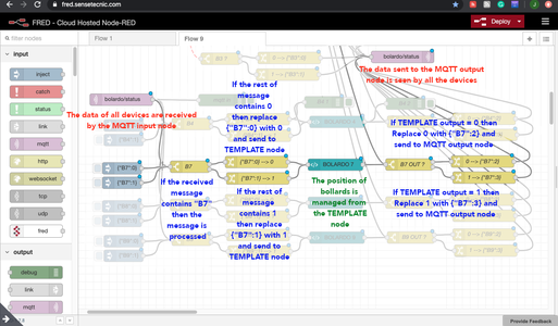


These are the images of the NODE RED code of the Raspberry Pi that was configured as a master station.
We can distinguish three main blocks.
The first block (located at the top) is the code of the bollards that we have seen so far and that contains the TEMPLATE nodes with the animations.
The second block (located in the middle) is responsible for converting zeros and ones to messages that are sent and received by the MQTT node.
The third block (located at the bottom) is responsible for creating the "Virtual Bollards" of the other Raspberry Pi and for handling and converting the messages of the MQTT nodes into commands used by the TEMPLATE node.
Attachments
Step 34: NODE RED - BOX 2


In this Raspberry Pi only one Bollard was configured to receive MQTT commands.
Why?. Remember that the client has four bollards installed in his access area "A", so the client designated to use a Raspberry Pi (master station) for three bollards and this (box 2) only manages the remaining bollard, leaving the others as spare.
The function of the code is the same as indicated in the master station (box 1).
Attachments
Step 35: NODE RED - BOX 3


This Raspberry Pi (box 3) is the one installed in the access area "B" (the remote area) and handles the three bollards installed in that area.
The function of the code is the same as indicated in the master station (box 1).
Attachments
Step 36: CONTROL DASHBOARD


This is a simple but very useful dashboard to control a Raspberry Pi, it includes so far:
- CPU Temperature
- CPU Load %
- Free RAM %
- Disk Usage %
- Actions: Shutdown and Reboot buttons
You can download the source code from here.
Step 37: NETWORK & SECURITY

It is time to take the final steps.
SECURITY:
To configure application security, follow these steps:
We need to disable the WiFi network to avoid unauthorized access. To do this see the following link or this video.
NETWORK:
It is time to configure the network addresses provided by the client. To configure static IP addresses see this link.
Other link: How do I set up networking/WiFi/static IP address?
Step 38: FINAL PROGRAMS

Here are the complete programs of the three Raspberry Pi with all the components installed.
Step 39: LABELING


One of the last steps before delivering all the equipment to the user is to properly label it. For this, I designed some labels with the device identifier and the ID of each bollard it controls. I also put a QR code with contact information, date of development, as well as the hardware and software version.
I also made labels to identify each button, as well as labels indicating the IP address of each device.
Step 40: FACTORY ACCEPTANCE TESTING


Once all the modifications to the software are finished and before delivering the final product to the customer, it is necessary to perform what is called Factory Acceptance Tests (FAT). These are a series of tests in which the equipment is subjected to critical working conditions, for example: high or low operating temperatures, overload in the execution of applications, detect errors that occur when handling the equipment in conditions other than normal, etc.
One of the tests carried out for 72 hours was to keep the equipment at an operating temperature of 35 ºC and monitor the temperature reached by the CPU under these conditions. In all this time the Raspberry was able to operate normally with an average CPU temperature of 52 ° C and an average workload of 51%.
Once the FAT test phase is over, it is time to install the equipment at the customer's premises and make the final adjustments.
Step 41: INSTALLATION & SITE TESTING


One of the problems that arose during the installation of the boxes was that the ports assigned to the MQTT protocol were not enabled on the client's LAN, so the client's IT department had to be requested to enable the ports used by the MQTT protocol.
Once the IP addresses provided by the client were configured correctly, the tests were carried out to verify that all the installed boxes operated correctly.
In this stage, the security options were configured and the users and passwords of access to the boxes were created.
Step 42: CUSTOMER ACCEPTANCE TESTING
Once the installation and FAT tests are completed, it is time to call the customer to test the system.
Step 43: DOCUMENTATION AND DELIVERY TO THE CUSTOMER


The last step after everything went well, is to deliver the documentation of the bollard controllers: User manuals and technical sheets.
In addition, one as a designer has to keep a copy of all the information necessary for the project, as well as the source code of each of the Raspberry Pi installed. We must remember that the team has a 1 year warranty and we have to have everything at hand in case there is a problem at this time.
UPDATE: It has been a year since the equipment was installed and it is still working perfectly.
I hope this INSTRUCTABLE gives you ideas for your next projects.
Attachments

Second Prize in the
Raspberry Pi Contest 2020

![Tim's Mechanical Spider Leg [LU9685-20CU]](https://content.instructables.com/FFB/5R4I/LVKZ6G6R/FFB5R4ILVKZ6G6R.png?auto=webp&crop=1.2%3A1&frame=1&width=306)


