

Introduction: Intelligent Braking System Prototype by Arduino


Hi, This Aditya kombe from EuphoLabs Hardware development community brought a new project that is a concept converted to Reality .Here we are making something that is visualized by many automobile companies like here's demo-
So we are making a demo prototype of such system that applies brakes proportional to the distance between car and obstacle. #ultrasonic #arduino #RC_car
Step 1: Making the Car Base.
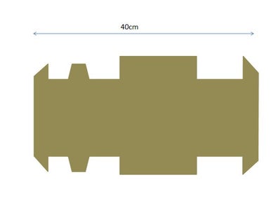
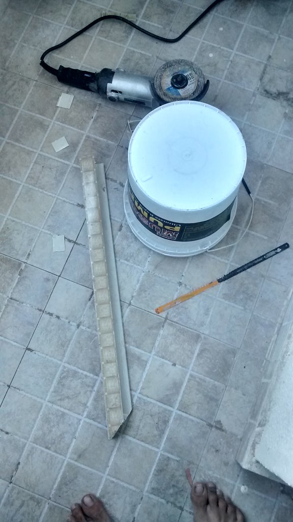
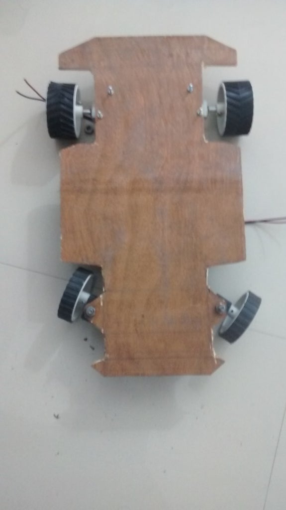
Take a plywood of 5mm or 7mm width and more than 50cm height. Cut it along as it is in fig 2 . Take measurement by calculations according to your wheels. Just remember the fact keep front wheel space more as we will design steering so calculate by moving wheels.Take a grinder and go on ....
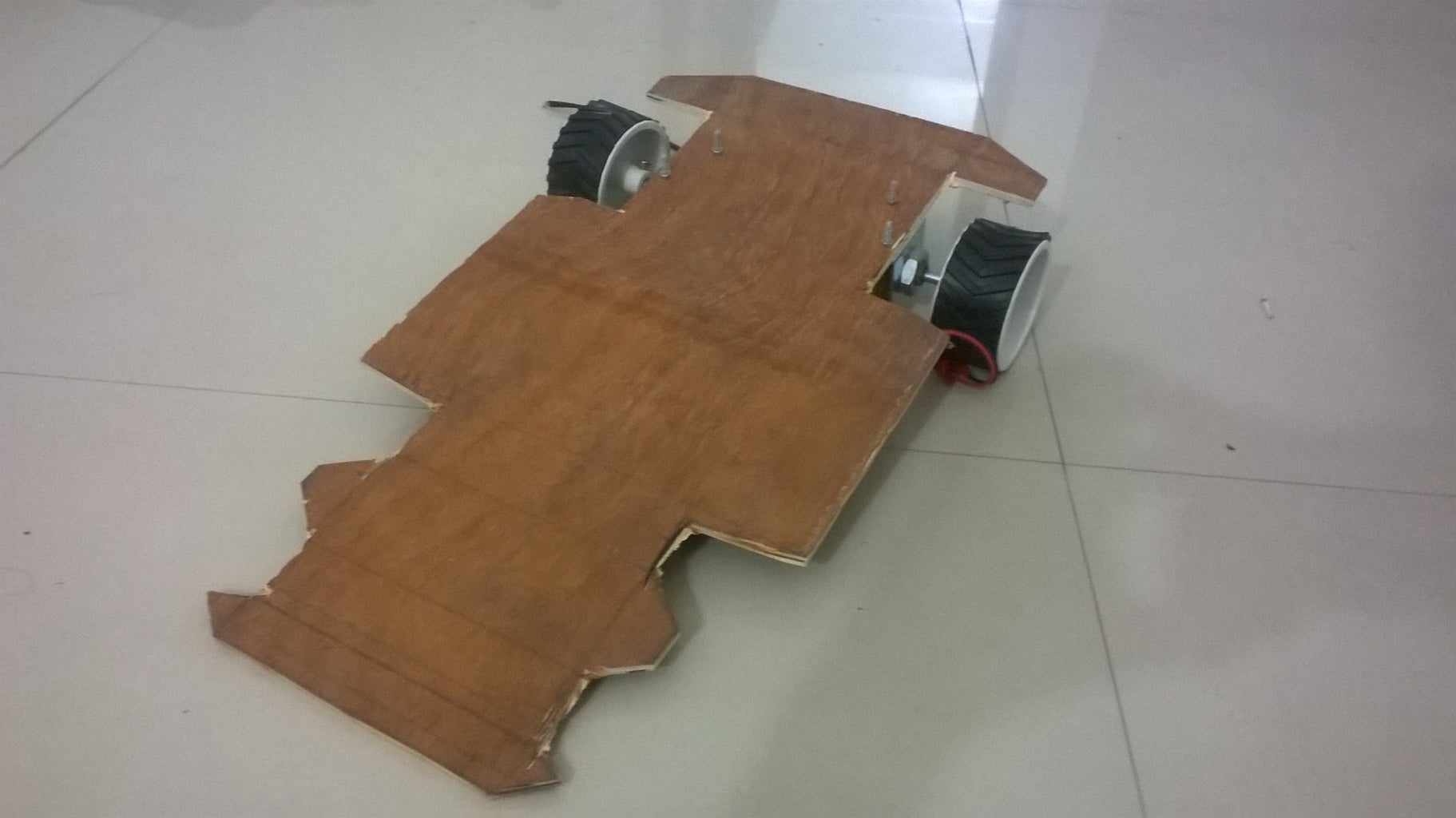
Step 2: Back Wheels Placement
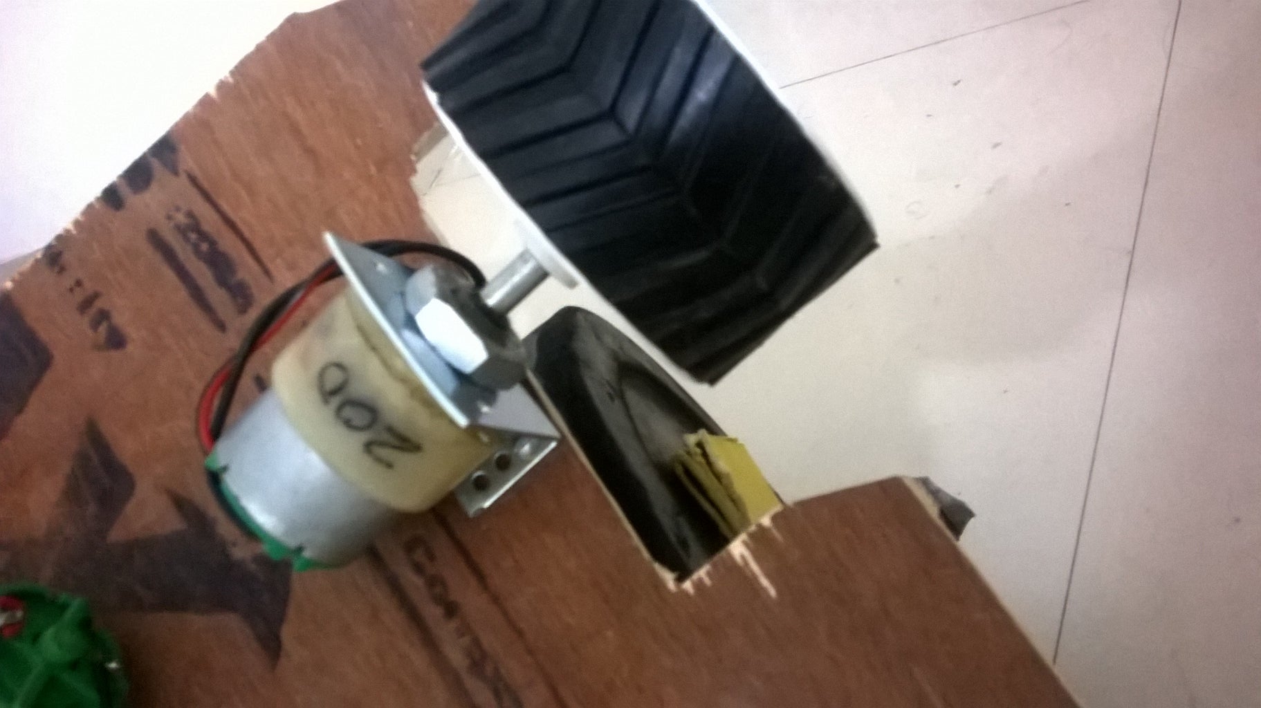

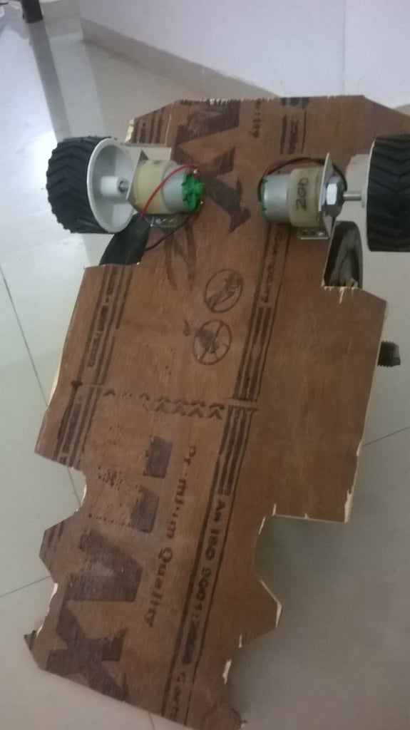
we will use 200 rpm or 100 rpm dc 12v motor , a L clamp screw hub , robotic wheel of 4cm x7 cm dimensions. fix L clamp on the corner and do it on both sides of symmetry.
Step 3: Steering Wheels!!!


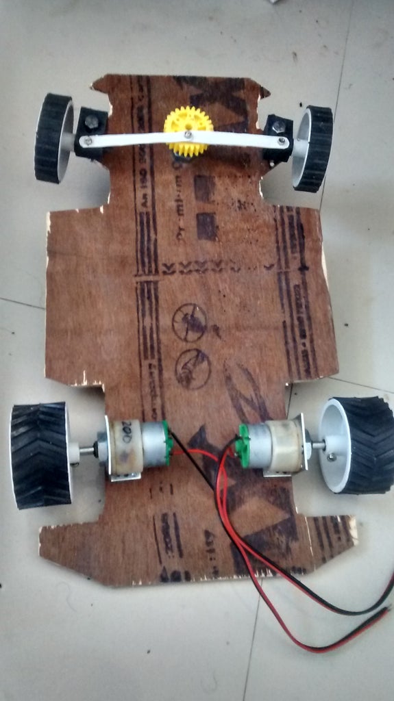
We will use a 15 rpm dc gear motor to Control steering wheels but you can use Servo motors also. We will need
1.A gear hub
2.Two thin long plastic sheets or hard metal string
3.Two rubber stopper or plastic strips.
4. four long bolts that fits into the wheel axis properly
5.Thin and Small bolts or screws
6.Two 2cm x 7cm wheels
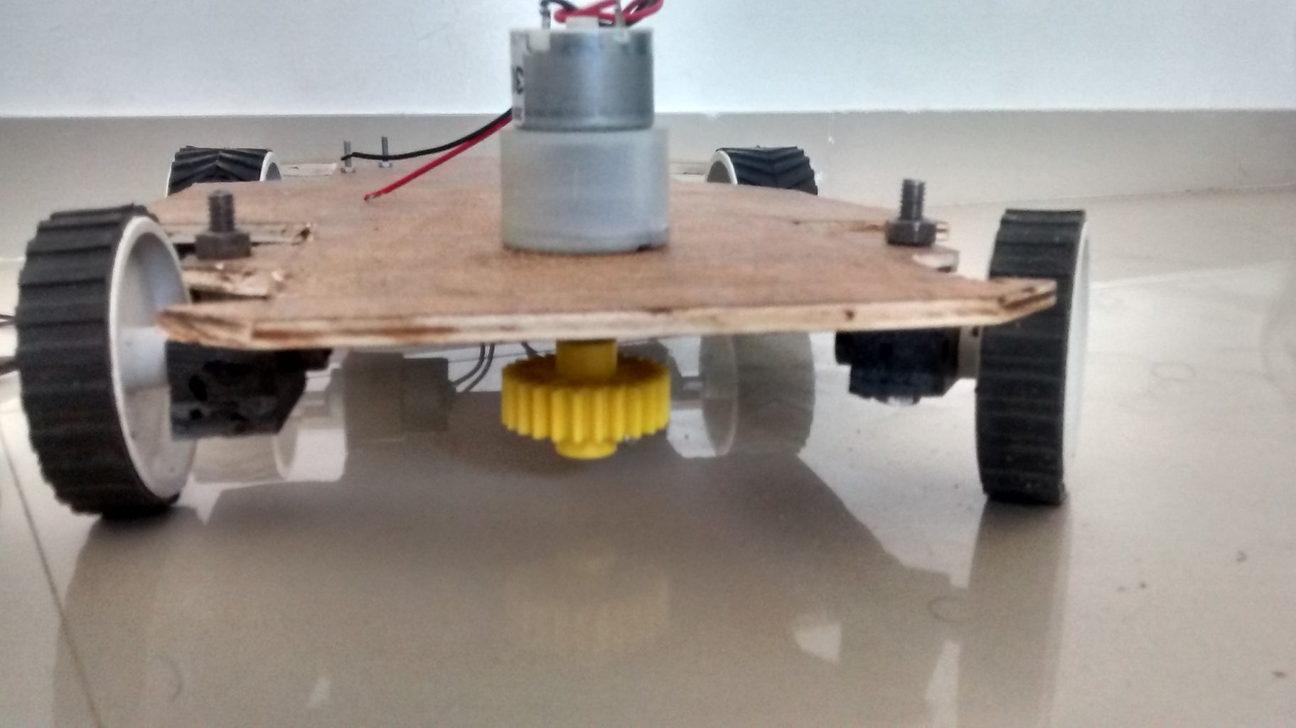
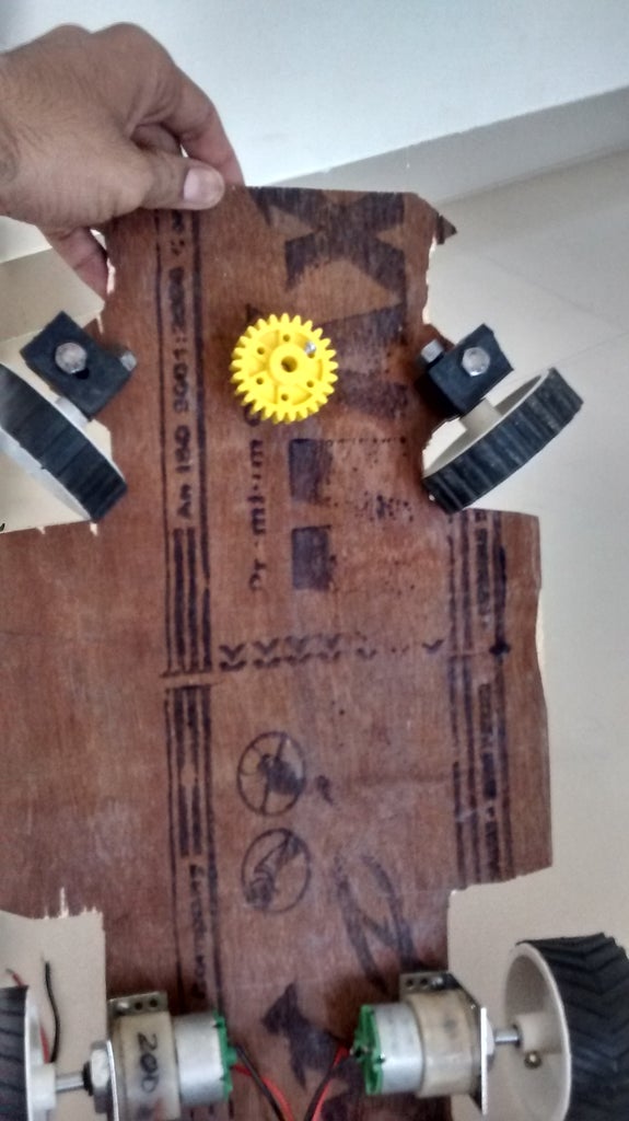
Rubber stopper can be the blocks of the wood as we are just creating a angular suspension to the front wheels. Just hole in them with drill and try to make a 90 degree L suspension for wheels as shown in fig no. 2, 3 ,and 4. Make hole equivalent to the Bolt in the car chassis as shown in the fig no. 5. Fix the wheel and Rubber stoppers to the chassis.Add a hole for the motor of slight larger equivalent to the neck of the motor in the center as shown in the fig. 6.
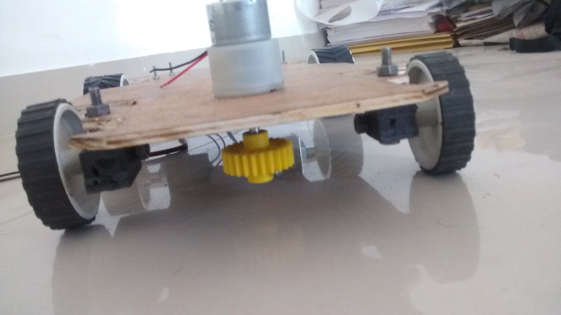
Fix the motor with gear hub . Make sure you shred gear head to plane by cutting of extra part for smooth steering.
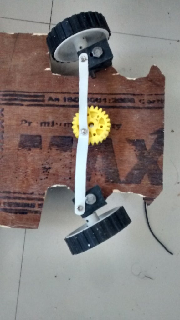
Add two more small holes on the edges of the stoppers to fox the plastic strips and get along the Gear for movement.Calculate the length of plastic strips accordingly.Fix the small hole with screw or Thin bolts as you wish.See the fig no. 10 in the step. I hope you don't break the strips in the trial if so make necessary steps to stop extra movement.
Step 4: Skippable TESTS!!! That May Be Quite Useful...
Since our Car chassis or model is Ready now we will move forward to- "ULTRASONIC SENSOR TEST".
we need
1.Arduino uno
2.L293d motor driver module
3.Toycar
(note*--- TEST-1 and TEST-2 are skippable)
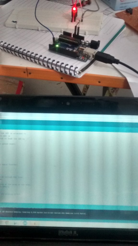
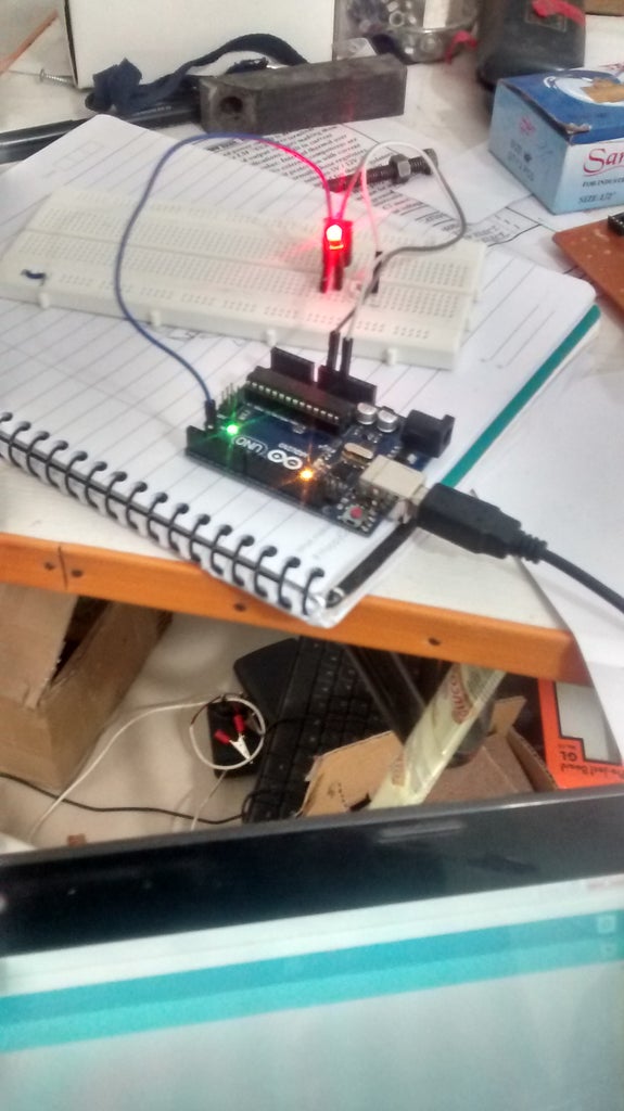
TEST-1
Our moto here in TEST-1 is to get reading from Ultrasonic sensor in centimeter in serial mode.See fig 1. We interfaced Ultrasonic sensor with arduino with pin configuration as-
trigPin 7
echoPin 6
vcc 5v
and gnd
and uploaded the below code test1.rtf a microsoft word file containing arduino code , copy , paste and upload please.
Judge the distance in serial code .
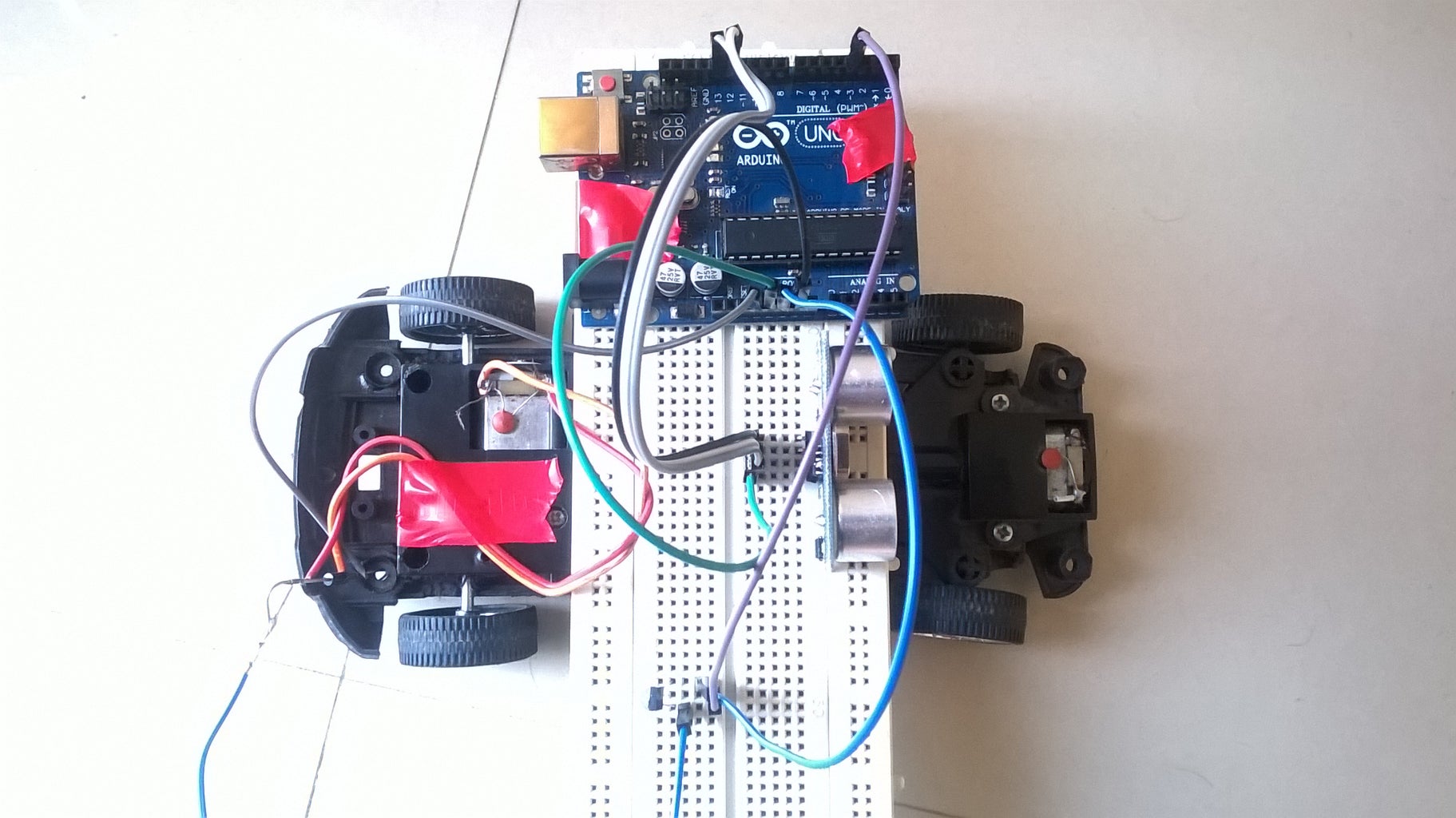
TEST-2
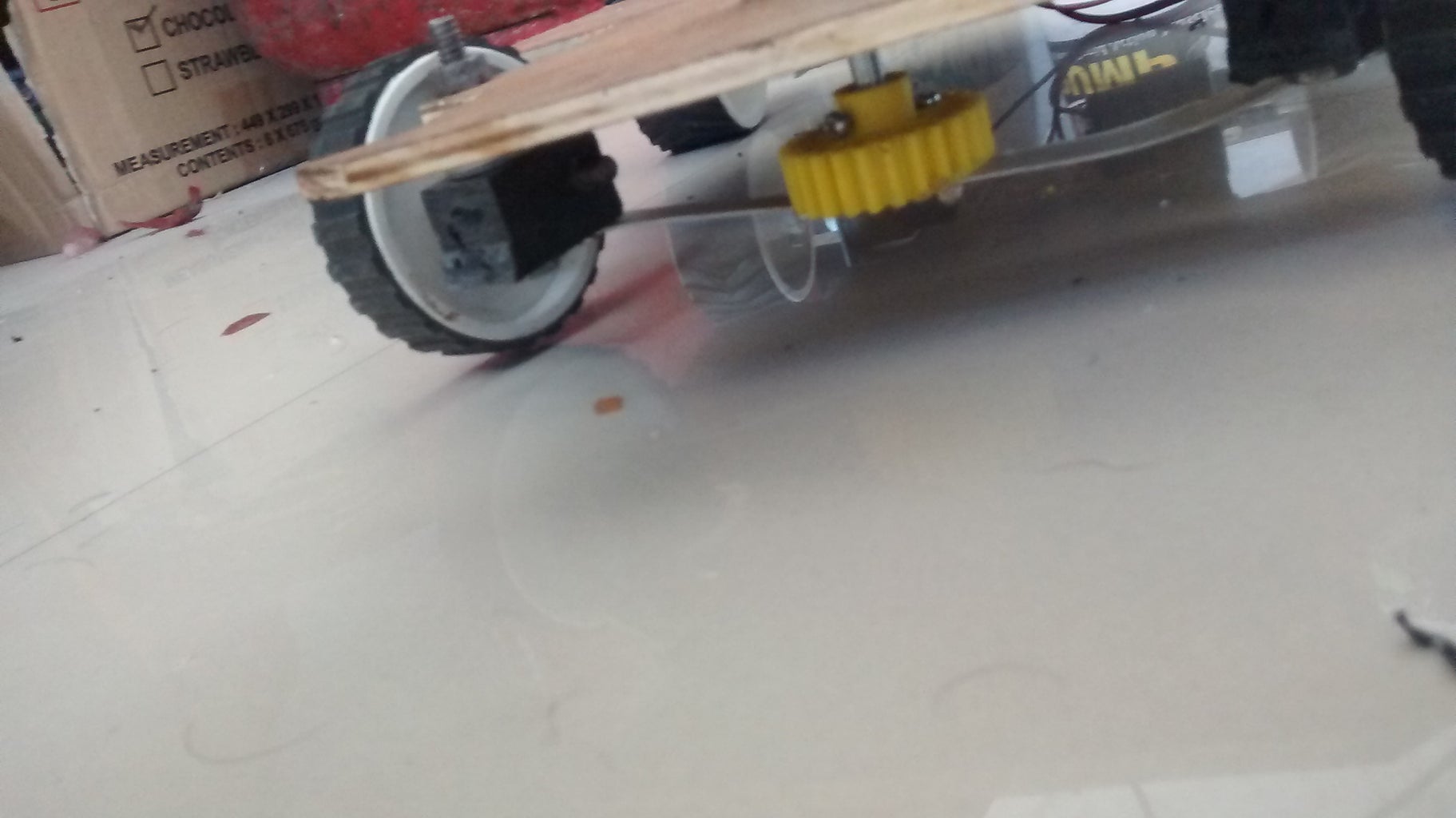
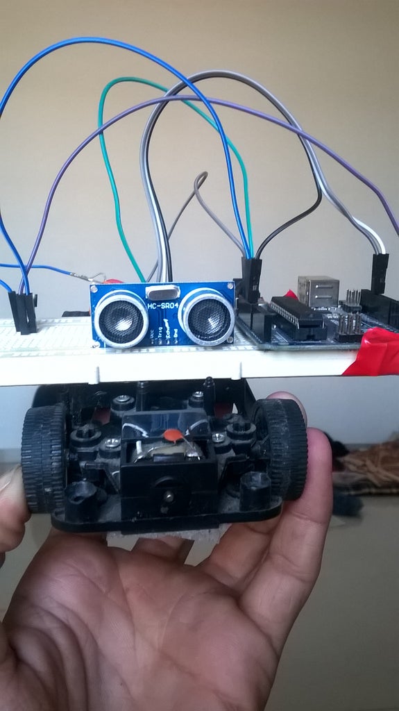
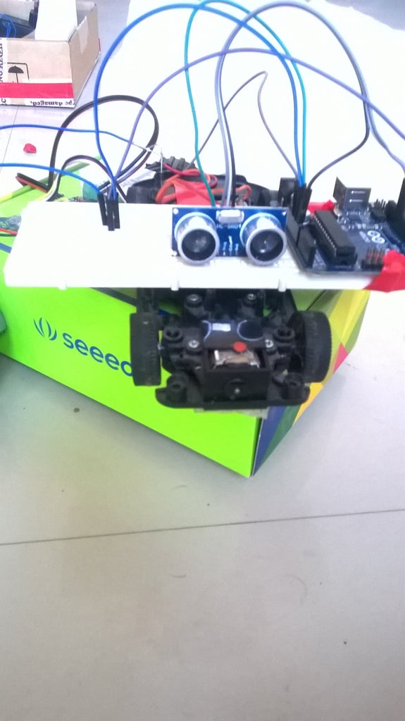
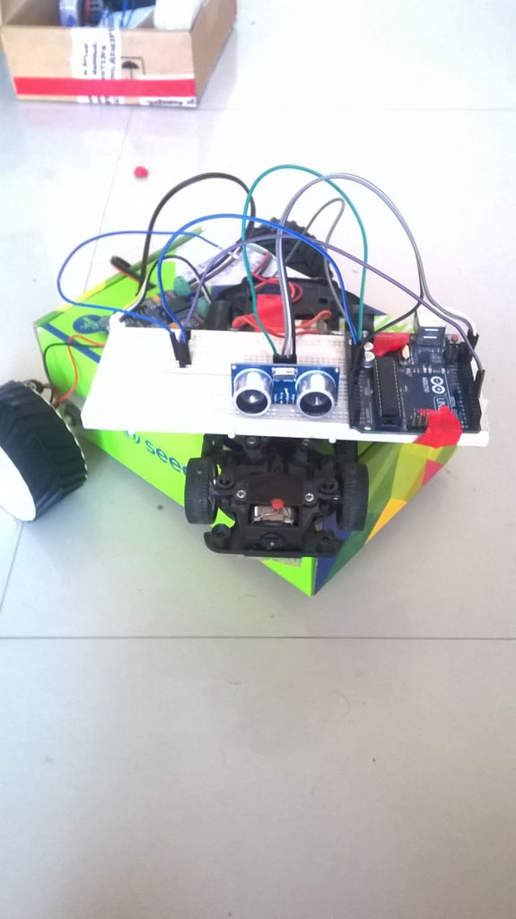
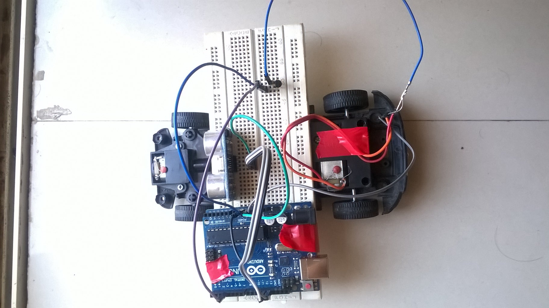
Take a toy car connect it to the motor driver(Rear wheel motor only) and for input connect the same arduino's pin no. 3 to the input. And upload the same code of TEST-1 again. Judge the distance and have trials. as shown from fig no. 3 onwards . (Notice the cool robot in the background i made out of groove kit box , well nothing to do with this project but notice how cool...how cool ! ! )..

Step 5: UNDERSTANDING THE CONCEPT , WHAT ACTUALLY ARE WE DOING HERE???
We are mapping the distance with ultrasonic ping sensor and regularly changing the PWM output to control speed of motor
WE use-
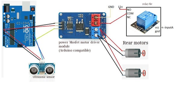
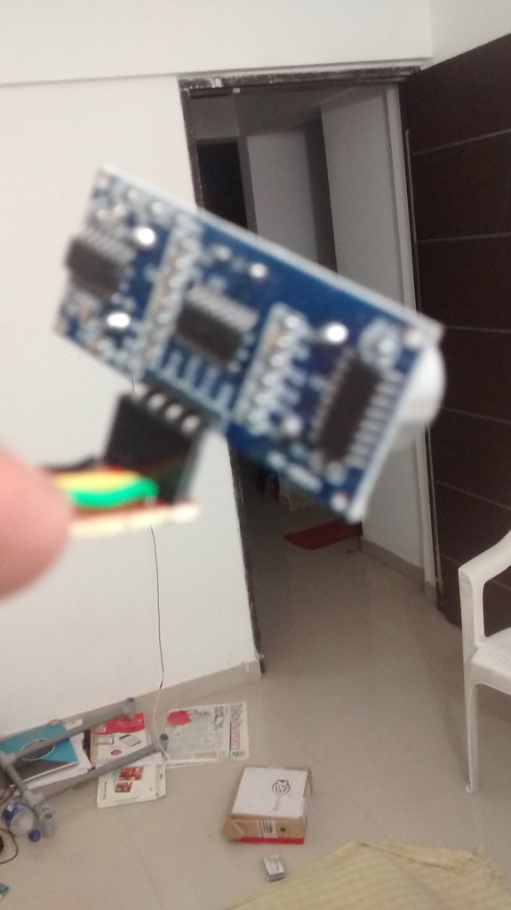
1. Mosfet based motor driver of input logic 5 v (get from ebay or dx.com)
and go for logic as shown in fig 1.
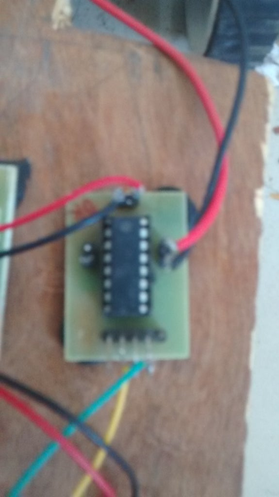
Whether if i made my own mosfet driver using optoisolator, IRF960 n channel ,and a copper clad pcb i recommend use a kit here.
Fig 1 here is the concept picture.
Step 6: Using RC!!
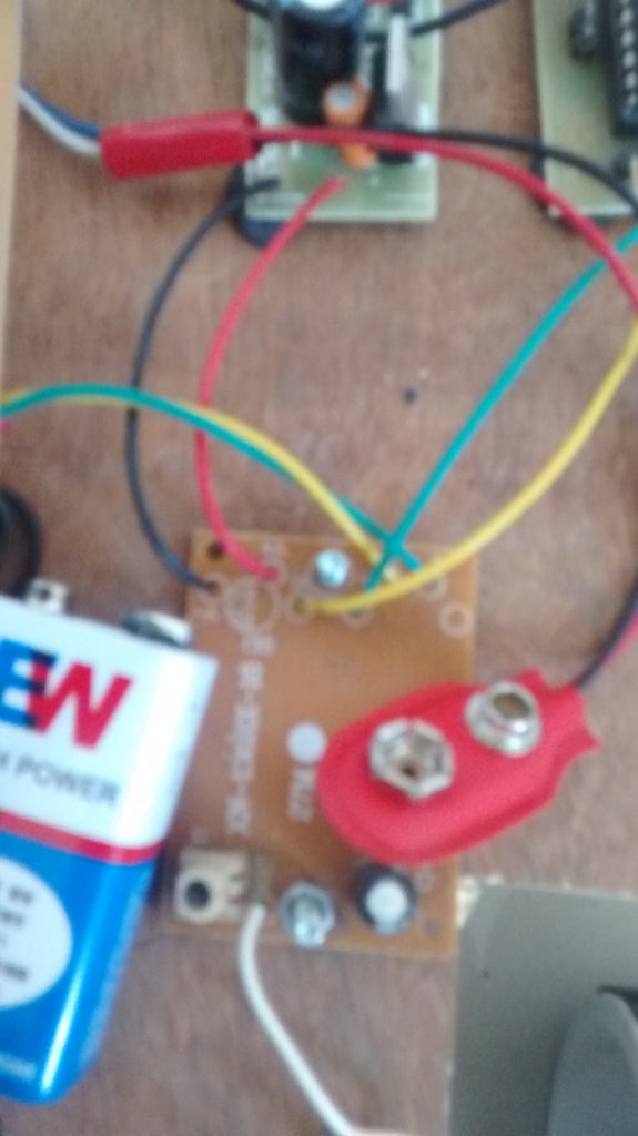
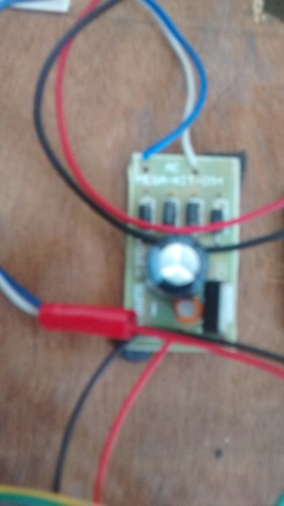
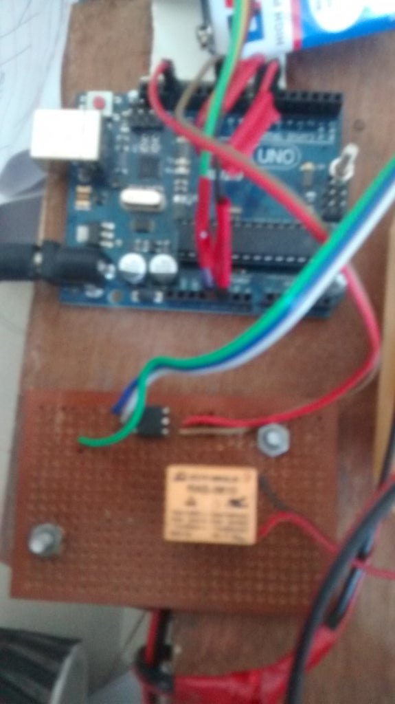
Hack a toy car - take out its wire from motor outputs from both the motors , battery unit and antenna wire(note * only a proper 5v operational, running(FWD and BCK) and steering(LEFT and RIGHT toy car only with good range).I got the one in fig 1. Add a 7805 5v Regulator assembly (Fig 2)to provide it a steady 5v supply. The FWD and BCK ie forward-backward motor wires is our inputA as you may have seen a input to the relay in concept picture of previous step in which we covered the understanding the concept part.(step 5 ).Connect a naked Relay or a Relay module to this motor as polarity doesn't matter here.The output of Relay will be same from the concept image.
Use a l293d motor driver module whose output will be connected to the 15 rpm steering motor and input given by LEFT and RIGHT RC kit outputs wire. shown in fig 3 of the step.Also test it to guaranty that RC remotes left is the steering motors left also.
Add a antenna to antenna wire.
Step 7: Ping Sensor Holder..


Make a ping sensor holder using a female pin hub and a piece of a perf board ,take the wires out and stick it up in front of the chassis.
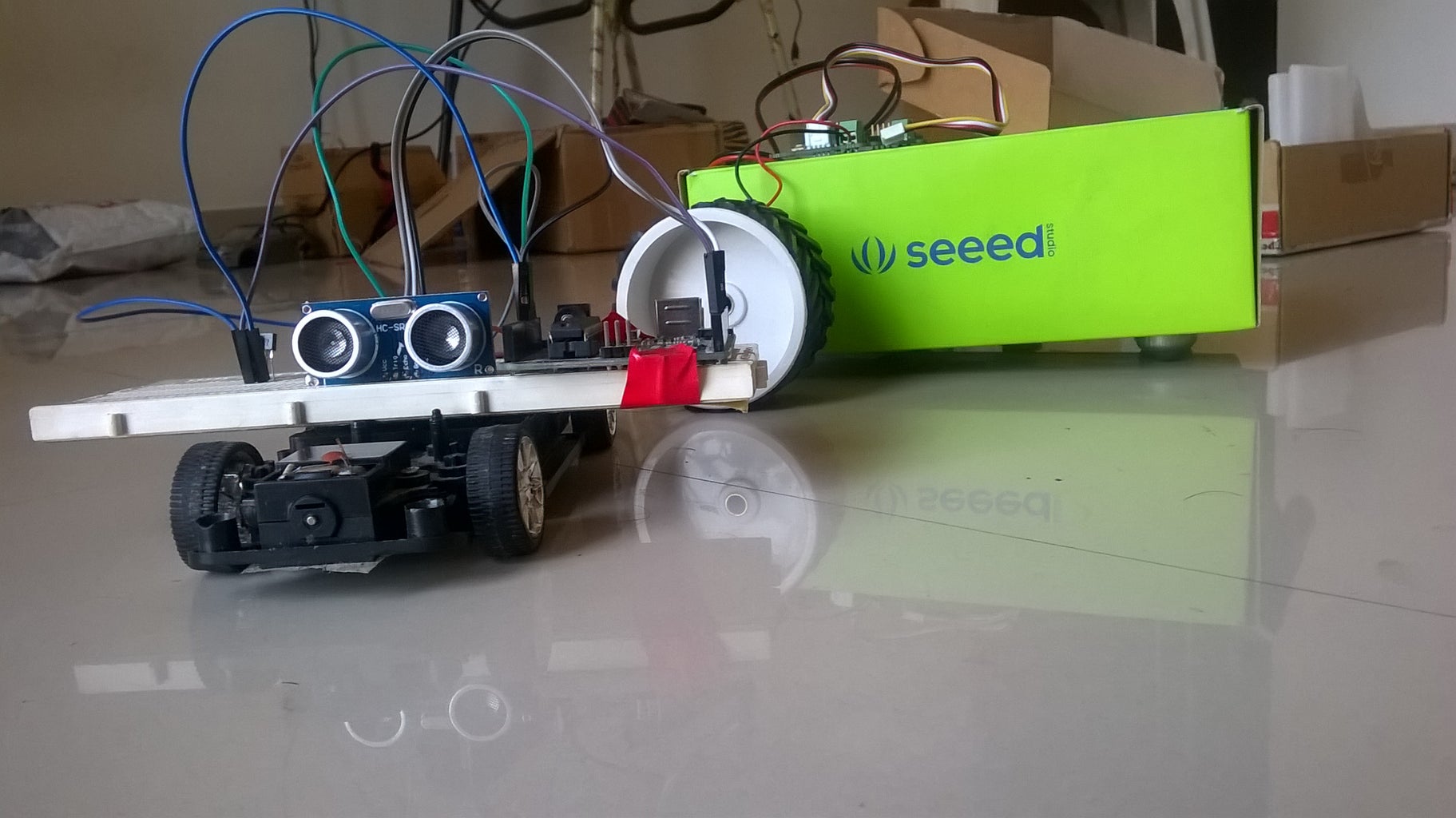
Step 8: And We've Done!!!!!!!!!

Upload the Final sketch given in the microsoft word file Final.rtf , copy-paste-Upload please.
and distances are adjustable.
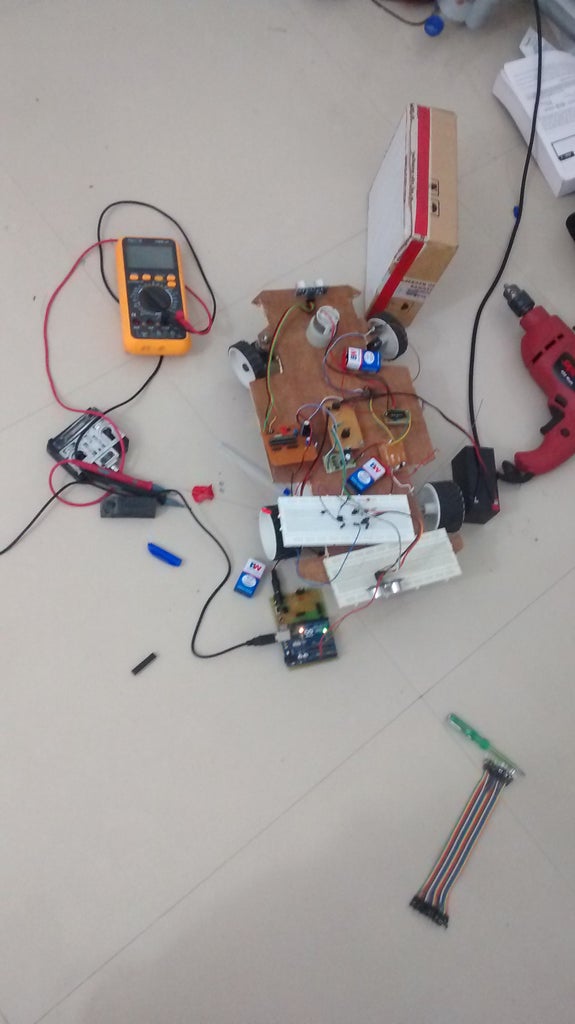
solder!! connect !! make it !!
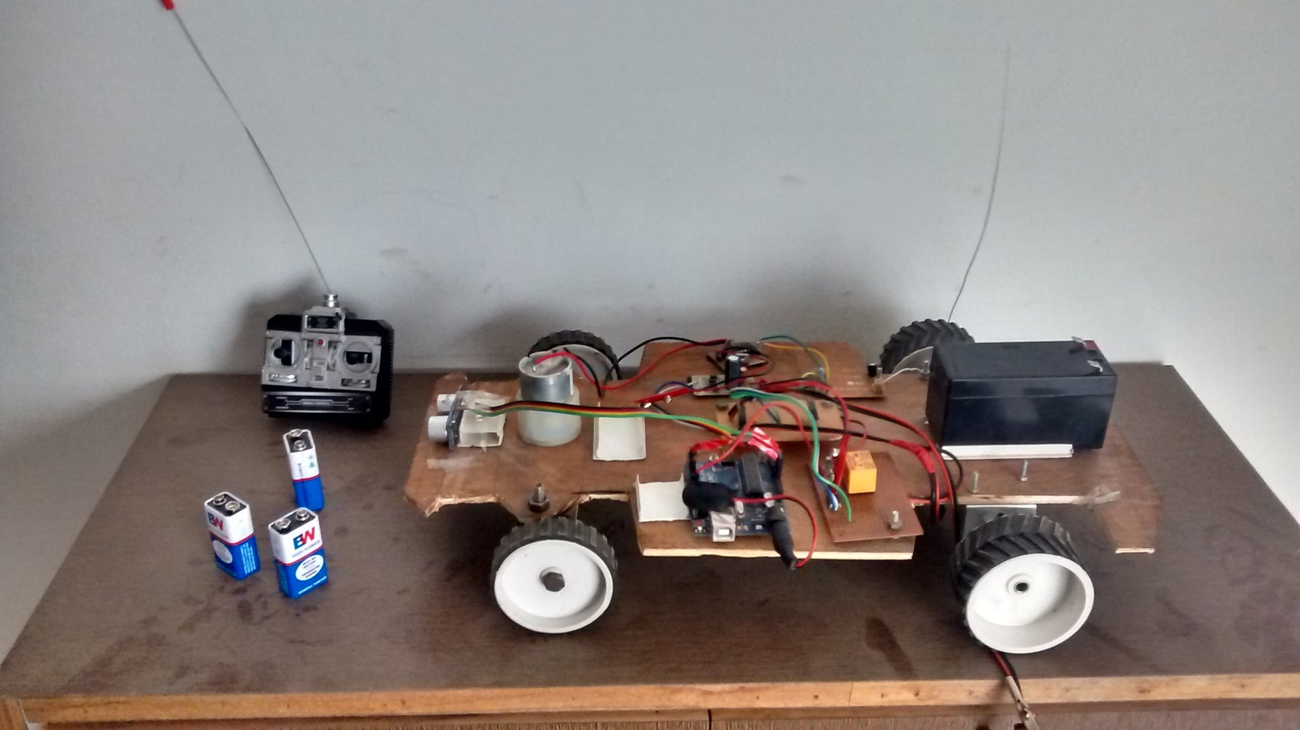
Add 9v batteries to two 7805 regulators , a 9v battery with dc male plug to UNO, A 12v DC motor to the Relay according to concept picture.
Battery Draining fast?? no problem give ultrasonic sensor its own power.
Add Backlights as your wish i left a pin on UNO that you find in the final sketch.
Play-Learn-Modify-Its yours!!
here are some videos-(there are really poor But model worked very well.....NO crashes at all ..)


Participated in the
Wood Contest 2016


