

Introduction: KeyChainino - the First Game KeyChain Programmable With Arduino

KeyChainino is a vintage game keychain programmable with Arduino where anyone can upload his own game just with the Arduino IDE.
If you really love Arcade Game, KeyChainino is for you!
It doesn't have any LCDs, but only 30 LEDs controlled by the Atmel ATtiny84. Surely you understand that an 14 pins microcontroller can't manage 30 LEDs, in fact i can drive these large number of LEDs with theCharlieplexing Matrix.
The real cool staff of KeyChainino is that you don't need to manage a tight charlieplexing matrix - really hard to handle - but you need to work only with a standard 6x5 Matrix.
In this way you can quickly program your own game!
The topic of this Instructables is how to make your own game for KeyChainino
Step 1: Connecting to KeyChainino

In order to upload your sketch to KeyChainino, you need to configure the newest Arduino IDE in the way descripted here: http://www.keychainino.com/how-to-program-keychainino/
What do you need:
- an Arduino (preferably the UNO, but the others versions still works) as ISP Programmer or an standalone ISP Programmer
- a 6-pole cable to connect the ISP Programmer to KeyChainino
After you have successfully upload the arkanoid first game, we can now talk about the sketch structure.
Step 2: General Sketch Explanation

If you haven't already done, download the arkanoid sketch from here
General sketch explanation:
This KeyChainino arkanoid-like game is based on a ball that bouncing on the "screen" (matrix LEDs) and a paddle used to avoid the falls of the ball in the bottom part of the screen.
The heart of the sketch is the function enabled by the overflow of the timer 1. This function is used for two things:
- Automatically update (in background) of the game values, like the ball position
- Updating the Charlieplexing Matrix according to a programmed matrix - called matrixState - that is used to turn on or off the LEDs and so to shows things on the screen.
I want to spend few words about the Charlieplexing Matrix.
The Charlieplexing Matrix - according to Wikipedia - is a technique for driving a multiplexed display in which relatively few I/O pins on a microcontroller are used to drive an array of LEDs.
Basically, with this technique we are able to drive more LEDs than the I/O pins of the microcontroller.
How? By connecting the LEDs in a particular way - described in the above article - you can drive the LEDs by changing the state of the microcontroller pins. You can turn on one LED by turning HIGH one pin and LOW another pin. The other pins must be in three-state, meaning that these pins must be put as INPUT.
Each time the timer 1 counter overflows - meaning that it's counter came back to zero - its overflow interrupt occur and its function updates the Charlieplexing matrix by reading the value of the 6x5 matrixState and put this value (1 or 0) to the specific LED.
Only one LED at time is putted ON, but whereas the overflow is too fast - more fast than the eye frequency reading - we have the feeling that all the LEDs are ON at the same time.
However you don't need to care about this charlieplexing function, because you only need to change the matrixState values to turn on or off the LEDs.
Here the matrixState. In this case all the LEDs are turned off.
bool matrixState[MATRIX_ROW][MATRIX_COL] = {
  {0, 0, 0, 0, 0, 0},
  {0, 0, 0, 0, 0, 0},
  {0, 0, 0, 0, 0, 0},
  {0, 0, 0, 0, 0, 0},
  {0, 0, 0, 0, 0, 0}
};
If you want to create a face, you can modify the matrixState in this way:
bool matrixState[MATRIX_ROW][MATRIX_COL] = {
   {0, 0, 0, 0, 0, 0},
   {0, 1, 0, 0, 1, 0},
   {0, 0, 0, 0, 0, 0},
   {1, 0, 0, 0, 0, 1},
   {0, 1, 1, 1, 1, 0}
};
Obviously you don't need to change the matrixState in this way. After i'll show you how you can do it with arrays.
Check out this post for more details about Charlieplexing.
Step 3: Analyse the Sketch Init

Now i explain to you, step by step, all of the lines of the sketch.
The first #include lines are used to import the avr specific code for handle, in order:
- Interrupt library to handle the interrupt from timer 1 and buttons. The interrupts of the two buttons are used to wake up the microcontroller after it goes to sleep to reduce power consuming.
- PROGMEM library is used to put constant variable to the FLASH memory instead of the RAM memory. It is used because all the variables used on the sketch are stored in the RAM memory of the microcontroller and, usually, the RAM is less than the FLASH memory.
So, when i use a large number of constant variables - like the numbers matrix - i need to put in the FLASH to conserve the RAM memory.
I want to inform you that the IDE of Arduino, usually, not shows if the RAM memory of the microcontroller is full. If you have filled the whole RAM, simply the sketch will crash at some point and you will be crazy because you don't figure out why it happens.
So, if you use large constant variables, like multidimensional array, please use PROGMEM. - Sleep library is used to put the microcontroller in a deep state where it consumes very low power.
- Power library is used to handle the power of the peripherals in the microcontroller - like the ADC, timers, etc. When we don't need those peripherals we shut down them.
Next we have the constant value for the matrix, the pins and the buttons:
#define MATRIX_ROW 5
#define MATRIX_COL 6
#define PIN_NUMBER 7
#define BUTTON_A 6 //pin 6 - PCINT6
#define BUTTON_B 8 //pin 8 - INT0
In Order:
- MATRIX_ROW is the number of the LEDs rows. In this case 5 LEDsper line.
- MATRIX_COL is the number of the LEDs cols. In this case 6 LEDs by column.
- PIN_NUMBER is the number of pins used for the 6x5 LEDs Charlieplexing Matrix.
- Button_A is the pin number of the left button. This button trigger the PCINT6 interrupt
Button _B is the pin number of the right button. This button trigger the INT0 interrupt.
Now we have the variables used for the Charlieplexing LEDs Matrix:
- pins[PIN_NUMBER] is an array that stores the 7 pins used for the Charlieplexing.
connectionMatrix[MATRIX_ROW][MATRIX_COL][2] is a multidimensional Array that shows the single Connection of each LED in the Charlieplexing Matrix.
The first number of the two numbers enclosed in the curly braces, is the Anode.
The second number is the Cathode.matrixState[MATRIX_ROW][MATRIX_COL] is the multidimensional array that indicates which LEDs must be turned on or off. If you change a single bit of this matrix, the corresponding LED is switched ON of OFF according to which bit you insert: 1 is ON, 0 is OFF.
This Matrix is always used in the sketch because to show object, like pad and ball, they must be wrote in this matrix. So you need to delete the previous position by putting the object coordinate in the matrixState to 0, and then you can write the new position by putting 1 to the new coordinates. Always in the matrixState.If you want to show a face in the LEDs matrix, you need to passing every bit of your face matrix to the matrixState. Magically the LEDs assumes your face matrix! :)
This because the Charlieplexing Matrix is automatically updated - with timer 1 overflow interrupt - according ONLY to the matrixState Matrix.
Step 4: Game Variables


Then we have the bar (pad) variables
barCurrentPosition[2][2] is the current bar position. It indicates the actually position of the bar on the board. The first bar dot is on the position 4,3 (ROW, COL) and the second dot of the bar is in the position 4,3 (ROW, COL).
- barNewPosition[2][2] indicates the future bar position variable. In this part of the sketch it is the same as the barCurrentPosition.
barX1, barY1, barX2 and bar Y2 stores the positions of the two dots in x and y (COL = x, ROW = y).
for example:
barX1 = barCurrentPosition[0,1]
It means that barX1 is egual to the second byte of the first group of byte of barCurrentPosition. So it's egual to 2.barY1 = barCurrentPosition[0,1]
It means that barX1 is egual to the first byte of the first group of byte of barCurrentPosition. So it's egual to 4.And so on.
Next the BALL's variables
- ballCurrentPosition[2] is the ball position in (ROW, COL), so it start in the position 0 ROW and random COL position.
ballNewPosition[2] is the future ball position.
- ballX and ballY are the the position in coordinates from the ballCurrentPosition. Used like the barX and barY
ballUpdatePositionCounter and ballUpdatePositionCONSTANT are used to decrease the speed of the ball updated by a specific function that is fired from the fast overflow interrupts. The ballUpdatePositionCounter is increased in the overflow function and, when it reaches the ballUpdatePositionCONSTANT, the updateBallPosition() function is fired.
So, if you want to increase the ball speed, you need to decrease the ballUpdatePositionCONSTANT.
Next we have these two game variables:
- score is the game score calculated in the number of collision between bar and ball
- gameStarted indicates if the game is started or not
Finally the matrix that shows the visual numbers of the score and the KeyChainino smile face:
for example this:
const PROGMEM bool KeyChaininoFace[MATRIX_ROW][MATRIX_COL] = {
 {0, 0, 0, 0, 0, 0},
 {0, 0, 1, 1, 0, 0},
 {0, 0, 0, 0, 0, 0},
 {1, 0, 0, 0, 0, 1},
 {0, 1, 1, 1, 1, 0}
};
This matrix called KeyChaininoFace is used to design my custom face by putting 1 or 0 where i want the LEDs are turned on or off, respectively.
After, in other part of the sketch, this face matrix will be passed in the matrixState matrix and will be automatically showed for real in the LEDs matrix.
Step 5: The Timer Overflow Interrupt


Here we talking about the timer 1 overflow and the two buttons interrupts.
As explained above, the ISR(TIM1_OVF_vect) function is executed when the overflow of the timer 1 occurs.
Inside this function we have two parts:
- The first part is used to update the ball position according to the ballUpdatePositionCounter.
- The second part is used to drive the Charlieplexing matrix according to the matrixState:
For each ROW and COL, first we check if the corresponding bit of the matrixState is 1 or 0.
After we change the state of the pins of the microcontroller to OUTPUT and HIGH or LOW according to the connectionMatrix.
We wait a little bit microseconds to permits to light up the LEDs, and next we turn off these LEDs by putting the corrisponding pins to INPUT.
Otherwise, if the bit of the matrixState is 0, we put the corresponding pins of the connectionMatrix to INPUT.
At the start and at the end of this function, we, in order, disable and activate the global interrupt because, since the timer overflow is too fast, we need to pause it while it does all the code in the function.
The other two functions, ISR(PCINT0_vect) and ISR(INT0_vect), actually don't do anything. It's just declared to use the interrupt of the two buttons to wake up the microcontroller.
If you want to learn more about the timer overflow interrupt, check out my post here.
Step 6: The Setup Function

the setup() function:
for (byte i = 0; i < PIN_NUMBER; i++) {
    pinMode(pins[i], INPUT);
}
with this for cycle we set all the pin used for the LEDs matrix to INPUT. This because the Charlieplexing matrix turn off the LEDs by putting his pins to INPUT.
pinMode(BUTTON_A, INPUT_PULLUP);
pinMode(BUTTON_B, INPUT_PULLUP);
with these two function we enable the pullup resistor for the two buttons. So, when one button is pressed, his state become LOW.
cli();
we disable global interrupts to set all the interrupts that we need.
TCCR1A = 0; // set entire TCCR1A register to 0
TCCR1B = 0; // set entire TCCR1A register to 0
TIMSK1 |= (1 << TOIE1); // enable Timer1 overflow interrupt:
TCCR1B |= (1 << CS10); // Set CS10 bit so timer runs at clock speed: (no prescaling)
With these functions we set the timer overflow interrupt. It is used to update the Charlieplexing Matrix.
I have written a post here that explain exactly how it works.
bitSet(GIMSK, PCIE0); //enable pingChange global interrupt
This function enable the global pinChange interrupt used for the button B interrupt.
In the setup() function we don't enable the interrupts for the A and B buttons. We enable they in the goSleep() function. This because we use the interrupts for the buttons only for wake up the microcontrollers after it goes to sleep.
ADCSRA &= ~bit(ADEN); //disable ADC <br>power_adc_disable(); // disable ADC converte
power_usi_disable(); // disable USI
These functions disabling all unnecessary peripherals to reduce power consuming.
sei();
Now we can enable the global Interrupt.
showKeyChaininoFace(); //show KeyChainino smile face
delay(500);
clearMatrix(); //clear the Matrix
gameStarted = true; //Start the game
Here we show the KeyChainino face by calling the showKeyChaininoFace() function and then we clear all the LEDs.
After that we set the gameStarted variable to true. In this way our functions knows that the game is started.
Step 7: The Loop() Function

Here we are to the loop() function.
In this function we only check if the gameStarted variable is true or false.
If it's true we execute the game() function. Otherwise we execute the endGame() function.
The game() function only trigger the updateBarPosition() that checks the status of the two buttons and consequently change the bar position.
The endGame() function:
- shows the score by passing the score variable to the showScore() function.
- clears the LEDs matrix with clearMatrix() function
- shows the KeyChainino face with showKeyChaininoFace() function
- Goes to setup the sleep function by using the goSleep() function.
After that the microcontroller goes to sleep.
When it wakes up - by pressing one of the two buttons - it proceeds to reset all the game variables using the resetGame() function.
Step 8: How Update the Ball Position


The updateBallPosition() is fired from the owerflow interrupt of the timer 1 and is used to update the position of the ball.
Here we are:
//change ball position depending on the ball direction
ballY = ballCurrentPosition[0] + ballDirection[0];
ballX = ballCurrentPosition[1] + ballDirection[1];
these instructions update the two variables ballX and ballY according to the ballDirection variable.
As explained above, the ballDirection can assume this values:
Direction
//Y: 0 = STOP, -1 = UP, 1 = down
//X: 0 = STOP, 1 = RIGHT, -1 = LEFT
int ballDirection[2] = {1, 0};//Y, X  indicates the direction where the ball is going
So, initially we add the current ball position to the ball direction.
This simplifies they way to manage the ball direction because the matrix ROW, for example, goes from 0 to 5 from Top to Bottom while the matrix COL goes from 0 to 6 from Left to Right.
This means that if the ballDirection is egual to {1,0},
ballY = ballCurrentPosition[0] + ballDirection[0];
//ballCurrentPosition[0] + 1 = ball goes down
ballX = ballCurrentPosition[1] + ballDirection[1];
//ballCurrentPosition[1] + 0 = ball takes is vertical position.
Now we have updated the BallX and BallY variables, but not the actually position of the ball in the matrix.
This because first we want to check if the ball makes some collision with the matrix border or the bar.
 //checkCollision
  if (ballY >= MATRIX_ROW - 1) { // ball touched bottom
    ballY = MATRIX_ROW - 1;
    if (ballX >= MATRIX_COL - 1) {
      ballX = MATRIX_COL - 1;
    }
    if (ballX <= 0) {
      ballX = 0;
    }
    if (ballX == barCurrentPosition[0][1] || ballX == barCurrentPosition[1][1]) { //ball touched bar
      ballDirection[0] = -1;
      ballDirection[1] = random(-1, 2);
      score++;
    } else { //ball touched bottom = END
      //END GAME
      ballDirection[0] = 0;
      ballDirection[1] = 0;
      gameStarted = false;
    }
}
else if (ballY <= 0) { //ball touch top
ballY = 0;
if (ballX >= MATRIX_COL - 1) {
ballX = MATRIX_COL - 1;
}
if (ballX <= 0) {
ballX = 0;
}
ballDirection[0] = 1;
ballDirection[1] = random(-1, 2);
}
else if (ballX >= MATRIX_COL) { //ball touched right
ballX = MATRIX_COL - 1;
if (ballY >= MATRIX_ROW - 1) {
ballY = MATRIX_ROW - 1;
}
if (ballY <= 0) {
ballY = 0 ;
}
ballDirection[1] = -1; }
else if (ballX <= 0) { //ball touched left
ballX = 0;
if (ballY >= MATRIX_ROW - 1) {
ballY = MATRIX_ROW - 1;
}
if (ballY <= 0) {
ballY = 0;
}
ballDirection[1] = 1;
}These functions match the ball position to the borders of the matrix.
If the balls touches the upper and left or right border, the balls bounce because we change its direction.
Now we update the matrixState with the ball new position in this way:
//update position   ballNewPosition[0] = ballY;
ballNewPosition[1] = ballX;
//delete current ball Position
matrixState[ballCurrentPosition[0]][ballCurrentPosition[1]] = 0;
//set current bar position to new position
ballCurrentPosition[0] = ballNewPosition[0];
ballCurrentPosition[1] = ballNewPosition[1];
//show new bar Position
matrixState[ballNewPosition[0]][ballNewPosition[1]] = 1;
First we clear the previous ball position by clearing its position in the matrixState array.
Next we set the new ball's position in the matrixState.
Step 9: Updating the Bar (paddle) Position


This function is fired by the loop() function.
First we check if a button is pressed.
If it is, we change the bar position according to which button was pressed.
//depends on which button is pressed, change the bar position
// to left (button A) or right (button B)
  if (!digitalRead(BUTTON_B)) {
    delay(80);
    if (!digitalRead(BUTTON_B)) {
      barX1++;
      barX2++;
    }
  }  if (!digitalRead(BUTTON_A)) {
    delay(80);
    if (!digitalRead(BUTTON_A)) {
      barX1--;
      barX2--;
    }
  }
Now we check if the bar touches the border of the screen and, if it is, we fix its position.
if (barX2 >= MATRIX_COL) {<br>    barX2--;
    barX1--;
  }
  if (barX2 == 0) {
    barX1++;
    barX2++;
  }
Now we really show the bar in the LEDs matrix by updating the matrixState.
//changing only X Ax
barNewPosition[0][1] = barX1;
barNewPosition[1][1] = barX2;
//only if the bar position is different
  // (means that the button was pressed)
  if (barNewPosition[0][1] != barCurrentPosition[0][1]) {
  //delete current bar Position
    matrixState[barCurrentPosition[0][0]][barCurrentPosition[0][1]] = 0;
    matrixState[barCurrentPosition[1][0]][barCurrentPosition[1][1]] = 0;
  }
  //set current bar position to new position
  barCurrentPosition[0][0] = barNewPosition[0][0];
  barCurrentPosition[0][1] = barNewPosition[0][1];
  barCurrentPosition[1][0] = barNewPosition[1][0];
  barCurrentPosition[1][1] = barNewPosition[1][1];
 //show new bar Position
  matrixState[barNewPosition[0][0]][barNewPosition[0][1]] = 1;
  matrixState[barNewPosition[1][0]][barNewPosition[1][1]] = 1;
We refresh the bar position on the matrixState only if the bar position is different from its old position.
This to prevent an annoying flickering.
Step 10: Showing the Score

The score of the game is calculated on how many times the ball bounces on the bar.
So, when the ball touches the botton screen - and not the bar - we end the game and the score will be showed.
We pass the score to the function: showScore(byte score).
Let's see the code:
clearMatrix();
char scoreChar[5]; //char were to put the score number
//converting the score to scoreChar
  String str = String(scoreNumber) + ' ';
  str.toCharArray(scoreChar, 5);
  for (char c = 0; scoreChar[c] != '\0'; c++) {
    for (int col = MATRIX_COL - 1; col >= 0; col--) {
      for (byte i = 0; i < MATRIX_COL; i++) { //put the charter into the matrixState
        for (byte j = 0; j < MATRIX_ROW; j++) { //as usual
          if (i >= col) {
            writeCharter(scoreChar[c], i, j, col);
          } else { //else, if col (i) is less than col, we shift the matrixState
            matrixState[j][i] = matrixState[j][i + 1];
          }
        }
     }
      delay(150);
    }
  }
First we clear the matrixState by firing the clearMatrix() function.
Next we convert the scoreNumber to a string and then to a charter.
This because we want to show the score in scrolling mode. In order to do that we get every char of the score number.
For example, if we want to show the number 15, converted to char array, we have:
scoreChar[5] = {'1','5',' ','\0',0}Where the chars int the first two position of the char array are the number.
The char in the third position is a space used to permit a correct vision of the score.
The char in fourth position is the end of the string. This charter is added automatically in every end of any string.
The last char, in the fifth position, is not used. It is used when the score number is higher than 99.
So, we show the scoreChar until we reach the charter '\0'.
We pass every char of the scoreChar to the writeCharter() function.
This function write the corresponding char number to the matrixState.
Since we want to scroll the number, we need to "write" in the matrixState only the part of the char number that we want.
In order to do that, we also pass to the writeCharter function, the position of the char that will be showed.
void writeCharter(char charterToShow, byte i, byte j, byte col) {
  if (charterToShow == '0') {
    matrixState[j][i] = (bool*)pgm_read_byte(&(zero[j][i - col]));
  }
So the writeCharter() function shows the number according to which number we pass to it.
Step 11: Reset the Game Values
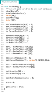
Ok, sadly we have loose the game. :-D
There's no time to lick our wounds! We need to reset the variables of the game to play again!
So we need to reset all the game variables to the original values.
Step 12: Other Functions

Here we have three function:
- The clearMatrix() function turn OFF all the LEDs in the Charlieplexing Matrix by clearing all the bit in the matrixState array.
- the fullMatrix() function turn ON all the LEDs in the same way of the clearMatrix() function
- the showKeyChaininoFace() copy the KeyChaininoFace matrix to the matrixState in order to show our favorite KeyChainino smile face.
Step 13: Now, It's Time to Sleep
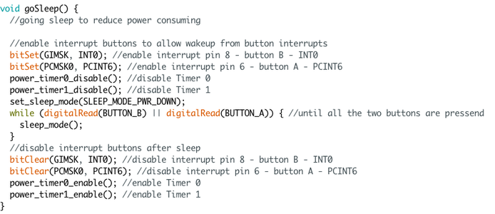
Well, now we have done the game and we can rest.
So we can enable the buttons interrupts in order to wake up the microcontroller when we push the two buttons at the same time.
We disable the timers because we are sleeping and we don't need to count the time :D and so we can save battery's energy.
Next we set the sleep mode and we go to sleep.
Only if the two button are pressed at the same time we wake up and we re-enable all the functions and timers.
Step 14: That's It!


Now we are able to upload the sketch to KeyChainino and we can enjoy the arkanoid-like game!
You can download the complete sketch here.
If you want to know more about KeyChainino, visit the website:

Runner Up in the
Arduino All The Things! Contest

Participated in the
Make It Glow! Contest

![Tim's Mechanical Spider Leg [LU9685-20CU]](https://content.instructables.com/FFB/5R4I/LVKZ6G6R/FFB5R4ILVKZ6G6R.png?auto=webp&crop=1.2%3A1&frame=1&width=306)


