

Introduction: L298 DC Motor Driver Demos/Tutorial


In this short series - I will attempt to show different methods for using the L298 H Bridge Motor Driver Board.
The L298 is commonly found in hobby and educational robots.
This was put together, not to show a complete working two wheeled robot, but to attempt to explain the ideas behind the operation. It is left up to the student the method, or combination of methods they would like to use in their project (robot). IT was purposely left to not show complete code, but the code could be easy to duplicate to other pins for two motor use.
The L298 can drive 2 DC Motors, these demos only use one motor, but can be duplicated on the remaining pins of the L298. SO for these demos, a 2 wire setup could be duplicated for 4 wires. A 3 wire setup could be duplicated for 6 wires. That is to say At a minimum you need 2 wires per DC motor. (This will * drive one motor)
And at minimum 4 wires are needed for 2 DC motors.
There are 5 parts:
- Part 1 of 5 - 2 Wire Direction Control, not using PWM.
- Part 1a - 2 wire direction and speed control using 2 PWM pins
- Part 2 of 5 - 2 Wire Direction Control and 1 PWM Pin speed using inverted logic
- Part 3 of 5 - 3 Wire Direction Control (Enable Pin) No Speed Control
- Part 4 of 5 - 3 Wire Direction Control, PWM on Enable pin for speed control.
- Part 4a - 3 Wire Direction Control, 2 PWM pins for Speed Control
- Part 5 of 5 - 3 Wire Direction Control, 1 PWM Speed Inverted Logic
- Part 5a - adding saftey and e-stop switches using enable pins, and interrupt pin.
The Demo Code can be found here: https://github.com/automation-technology-club/L298...
Please feel free to fork and improve the code as needed.
To follow along and duplicate you will need a
- L298 H Bridge Motor Driver
- Arduino UNO
- Dupont Wires (F/M, M/M)
- Small Breadboard
- DC Motor
I will let you source the parts yourself. I made decided to do it this way - for a couple of reasons. 1) It's a good way to learn where to find some good prices. (Start with Aliexpress, and eBay - but other online sources may be better for small quantity.) and 2) This isn't a complete project, it's a building block for a larger project. Because of this just having one DC Motor with one Wheel isn't very useful. The Arduino Uno may not be the best choice of microcontrollers for a larger project - it is however a good starting point.
Part 5a - We add a switch as a type of "safety or e-stop", This is just to show what could be done, not what should be done. (I will say this up front, the code example in 5a didn't work quite as expected. It did work just not quite the way I thought) I left it like this because again, this is a good example to learn and improve upon.
Step 1: What Is a H Bridge Motor Driver & What Is PWM.


According to Wikipedia:
An H bridge is an electronic circuit that enables a voltage to be applied across a load in either direction. These circuits are often used in robotics and other applications to allow DC motors to run forwards or backwards.
https://en.wikipedia.org/wiki/H_bridge
The L298 is a dual bidirectional motor driver, and allows for easy and independent control of two motors up to 2A each. It is ideal for robotic applications and well suited for connection to a microcontroller requiring just a couple of control lines per motor. It can also be interfaced with simple manual switches, Logic gates and relays.
Modularcircuits.com has a great tutorial on just how an H Bridge works. http://www.modularcircuits.com/blog/articles/h-bri...
The basics of it is the circuit looks like a "H" with the motor sitting in the center of the "H", each leg of the "H" has switches. By openning and closing switches on diagonal legs, you can cause the motor to spin in different directions.
On the microcontroller we can tell which switches what to do, but setting one of our two wires HIGH, and one of the wires to LOW. This will give us direction control of the DC Motor.
Basics of PWM (Pulse width modulation):
PWM is a technique for a digital pin to "simulate" an analog voltage. It does this by using a constant frequency of pulses and varying the on (Duty Cycle) and off times of the pulse. This is a very simplistic explanation of PWM.
Wikipedia has a full tutorial - https://en.wikipedia.org/wiki/Pulse-width_modulati...
For our purpose, it's a way to create what appears to be smaller voltages on one, of the drive pins. This causes the H Bridge to switch on and off quickly, and causes it to appear to change speed of the motor.
My video above shows some basic PWM, this is the same that will be used to make an apparent change in motor speed.
Step 2: Part 1 Direction Control, No Speed Control - Part 1a Add Speed Control Using 2 PWM Pins


Part 1:
Here we use the IN1 and IN2 pins of the L298 Motor Driver, we are not doing any kind of speed control at this point. The motor will run at full speed.
By setting IN1 to HIGH and IN2 to LOW we cause the motor to spin in one direction, if we reverse this and set IN1 to LOW and IN2 to HIGH, the motor will spin in the opposite direction. Setting both IN1 and IN2 to LOW will stop the motors. The ENA pin on the L298 board is left jumped.
Part 1a: Using TWO PWM PINS from the Arduino.
When we use PWM we add a "speed" element to controlling the motor. Like before. IF we set IN1 to HIGH and IN2 to LOW the motor will move in one direction. The difference this time, is how we make the "HIGH".
by doing an analogWrite(in1, 255); we cause the motor to still travel at full "speed". Any number between 0 and 255 will create the effect of speed. The motors I use have what I call a stall speed, this is the speed at which they stop working even if there is a positive (high) voltage on the line. For these motors I've found typically a PWM of 60 or less the motors will not spin. So from 60 to 255 and the motor will start slow and speed up. In the main loop you will see code like this:
for (speed = stallSpeed; speed  //Spin Motor in one direction with speed control
  analogWrite(in1, speed);
  digitalWrite(in2, LOW);
  delay(100); //let it up spin slowly
 }
You can see we change the digitalWrite(in1, HIGH); to analogWrite(in1, speed); This replaces the need for the HIGH.
And setting both IN1 and IN2 to either LOW or doing an analogWrite(IN1, 0); analogWrite(IN2, 0); will cause the motors to stop.
Step 3: Part 2 - Speed and Direction Using 2 Wires and 1 PWM PIN

Knowing that one of the IN pins needs to be HIGH and the other LOW - is there away to only use one PWM pins.
* On most micro-controllers don't supply a lot of PWM pins, so using 2 of them for one motor could eat a lot of your PWM pins up.
For this demo, we will use Arduino Pin 3 which is a PWM pin for our "speed" control. Pin 3 is connected to the IN1 pin on the L298 board.
void loop() {
//Stop the motor analogWrite(in1, 0); digitalWrite(in2, LOW);
// Move one direction speeding up from stallSpeed to maxSpeed. (slow down)
for (speed = stallSpeed; speed //Spin Motor in one direction analogWrite(in1, speed); digitalWrite(in2, LOW); delay(100); //let it spin up slowly }
You can see in the above example, we are doing very much the same as we did in the previous example. And our motor moves with "speed" in one direction.
But what about the other direction? And what about speed in the opposite direction?
//Stop the motor
analogWrite(in1, 0); digitalWrite(in2, LOW);// move the opposite direction with speed going from maxSpeed to stallSpeed (slow down)
for (speed = maxSpeed; speed > stallSpeed; speed--) { //Spin Motor in the other direction analogWrite(in1, 255 - speed); //Notice what we did here - this is called inverted logic and lets us use just one PWM pin and 2 wires to drive a motor digitalWrite(in2, HIGH); delay(100); //let it spin down slowly } }
As you can see, we are subtracting our maximum PWM vaule (255) from our "speed" vaule, the net result of this is for IN1 to appear to be driven LOW(er) than the IN2 pin. IN2 is now a HIGH.
Our loop has the speed starting off at our Maxspeed (255) when you take 255 - 255 you get 0 or a LOW.
As our loop progress the loop "speed" vaule drops to 60, when you subtract 255 from 60 you get 195, and the effect is the same as if we wrote a "60" to the IN1 pin. It's the difference between the HIGH (255) and the LOW (195) or again 60.
This is called Inverted Logic.
The rest of the demos are all based on these three ideas, NO PWM, using 2 PWM PINs, and Inverted Logic.
Step 4: Part 3 - Using the Enable Pin - Direction Control.

This is very similar to Part 1 - we are not going to use any PWM for this demo.
The enable pin is used to "Enable" the motor - in my mind this is a type of Safety or emergency cut off. And later we will explore a couple of different ways we can use Enable pin for these reasons. But for now, the we just had a 3rd pin (ENA) to the controller. When this PIN is brought HIGH, and IN1 is HIGH and IN2 is LOW the motor will move at full speed. When the ENA PIN is brought LOW, but IN1 is still HIGH and IN2 is still LOW the motor will stop (and most of the time quickly).
In the PART 3 Demo code, we replaced using the IN1 and IN2 to stop the motor, and are just using the ENA pin to stop the motor. This works but from a safety stand point, we don't know the state of the IN1 and IN2 pins and placing a HIGH back on the ENA pin could create a safety issue. SO it is better to set IN1 and IN2 to LOW to stop the motor.
void loop() {  //Stop Motor using just the enable Pin
  //This is not the best way to do this since if we re-enable this pin we don't know what the state of the motors are.
  //This works well for this demo so we can see how the enable pin works.
  digitalWrite(enA, LOW);
delay(5000); //wait about 5 seconds between movements

  //Spin Motor in one direction

  digitalWrite(in1, HIGH);
  digitalWrite(in2, LOW);
  digitalWrite(enA, HIGH); //if we put the enable at the end of the motor control, we can change the state of the in1 and in2 while the motor is stopped.
  delay(5000); //let it spin for about 5 seconds
* However for this demo it's enough to show how it works.
Step 5: Part 4 - Speed Control Using the ENABLE PIN

For this demo, we are going to use the one PWM pin connected to the Enable Pin. We can use the Enable Pin for motor control. The idea would be that the motor is switched on and off creating what appears to be a speed.
The wiring for this demo is the same as in part 3, so it's just some minor changes in the code.
Again, I am using just the Enable Pin to stop the motor, This still could create a Safety issue.
* Personally I don't think this is the best way to control a motor, I've included it as a learning tool.
void loop() {
//Stop Motor using just the enable Pin //This is not the best way to do this since if we re-enable this pin we don't know what the state of the motors are. //This works well for this demo so we can see how the enable pin works. analogWrite(enA, 0); delay(5000); //wait about 5 seconds between movements
// Move one direction speeding up from stallSpeed to maxSpeed. (slow down)
for (speed = stallSpeed; speed //Spin Motor in one direction digitalWrite(in1, HIGH); digitalWrite(in2, LOW); analogWrite(enA, speed); //if we put the enable at the end of the motor control, we can change the state of the in1 and in2 while the motor is stopped. delay(100); //let it spin up slowly }
You can see here that we are putting a PWM on the enA pin, and direction control is still done by using a HIGH and LOW on the IN1 and IN2.
// move the opposite direction with speed going from maxSpeed to stallSpeed (slow down)
for (speed = maxSpeed; speed > stallSpeed; speed--) { //Spin Motor in the other direction digitalWrite(in1, LOW); digitalWrite(in2, HIGH); analogWrite(enA, speed); //if we put the enable at the end of the motor control, we can change the state of the in1 and in2 while the motor is stopped. delay(100); //let it spin down slowly }
Step 6: Part 4a - Speed and Direction Control Using Two PWM Pins & Enable.

This is a duplicate of Part 1a with the addition of the Enable pin. The video is included with the video for Part 4.
This uses 2 PWM Pins, plus the enable pin.
Step 7: Part 5 Enable With Inverted Logic, Using a Switch for Safety


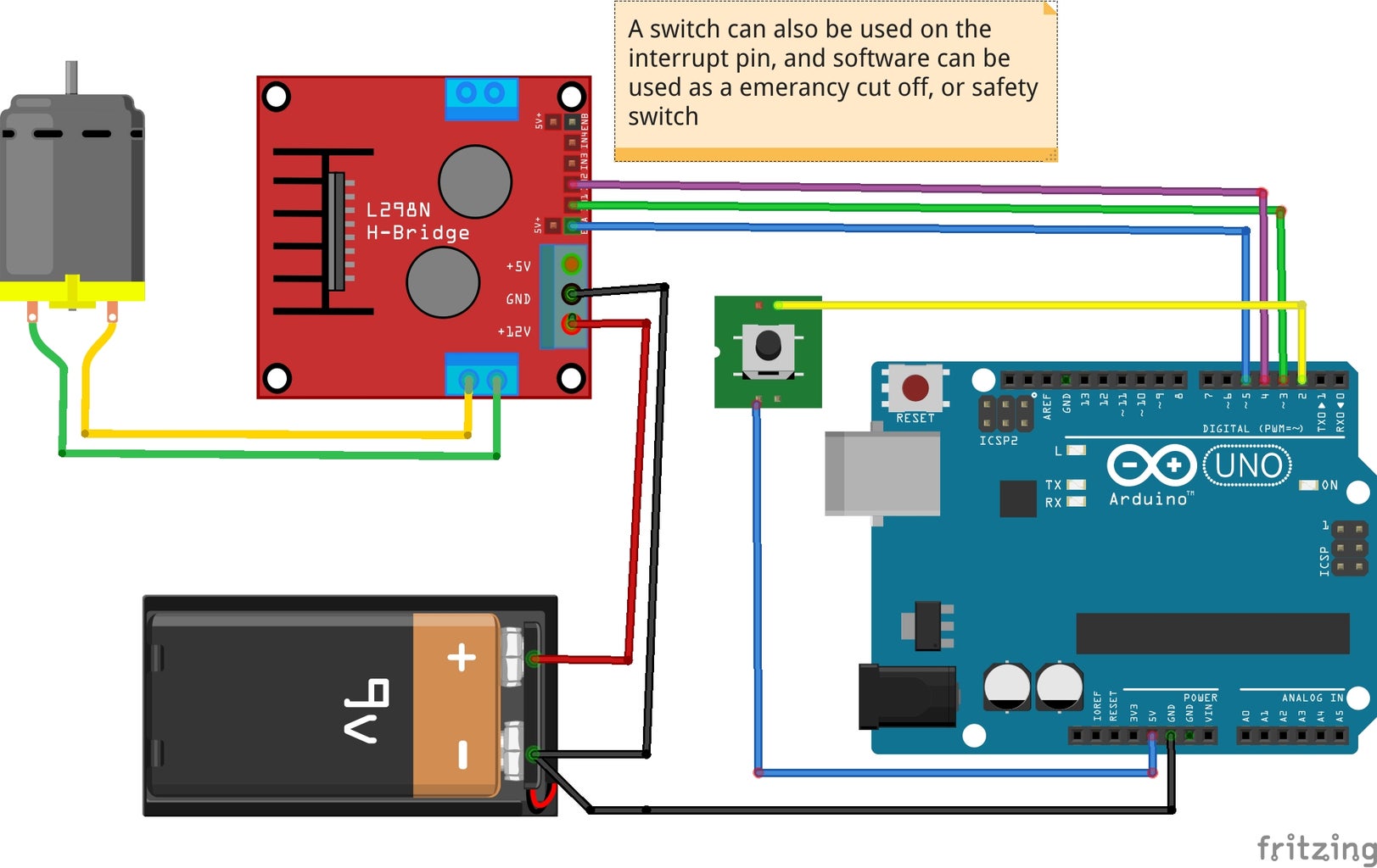
Part 5 is very much like Part 2, only we added the Enable Pin, it works very much the same way.
For safety switch, I wired a switch to the 5v of the Arduino, and to the Enable Pin on the L298 - the switch is normally closed - meaning it's providing 5v (HIGH) to the enable pin, unless the switch is pushed, then it goes to zero volts (LOW) and stops the motors. The video shows how this works. And depending on the application or device would depend on what type of switch is needed.
* I think a tilt switch could be used if the robot got flipped over, or bumper switches if it hits something
There are some draw backs to this, someone needs to interact with it to clear the switch error (Clear what ever cause it to stop the motors).
Lastly, I wired the switch to an interrupt pin on the Arduino. The idea here was to give some control back to the robot and still have an effect of Safety. This caused some timing issues, and you can see them in the video.
It was left in as a tool to learn and hopefully improve on my code.
I hope you found this interesting, and got something out of it. I also hope it was easy to follow, and will be easy to duplicate.
