

Introduction: LED Control Using ESP8266 WiFi Module- Internet of Things


The ESP8266 is a low-cost Wi-Fi chip with full TCP/IP stack and MCU (microcontroller unit) capability produced by the Shanghai-based Chinese manufacturer, Espressif Systems.
The chip first came to the attention of western makers in August 2014 with the ESP-01 module, made by a third-party manufacturer, Ai-Thinker. This small module allows microcontrollers to connect to a Wi-Fi network and make simple TCP/IP connections using Hayes-style commands. However, at the time there was almost no English-language documentation on the chip and the commands it accepted.The very low price and the fact that there were very few external components on the module which suggested that it could eventually be very inexpensive in volume, attracted many hackers to explore the module, chip, and the software on it, as well as to translate the Chinese documentation.The ESP8285 is an ESP8266 with 1 MiB of built-in flash, allowing for single-chip devices capable of connecting to Wi-Fi.
Step 1: The Basic Requirements for This Project Is Listed As Follows:-


(1) ESP8266 WiFi Module
(2) Arduino IDE
(3) Breadboard
(4) Jumper Wires
(5) USB-TTL Converter
(6) Power Source (3.3v DC)
(7) Wireless Internet Connection (WiFi)
(8) Web Server (you can use ours)
(9) LED
Step 2: What Is ESP8266?

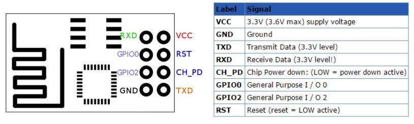
The ESP8266 is a low-cost Wi-Fi chip with full TCP/IP stack and MCU (microcontroller unit) capability produced by the Shanghai-based Chinese manufacturer, Espressif Systems.
The chip first came to the attention of western makers in August 2014 with the ESP-01 module, made by a third-party manufacturer, Ai-Thinker. This small module allows microcontrollers to connect to a Wi-Fi network and make simple TCP/IP connections using Hayes-style commands. However, at the time there was almost no English-language documentation on the chip and the commands it accepted.The very low price and the fact that there were very few external components on the module which suggested that it could eventually be very inexpensive in volume, attracted many hackers to explore the module, chip, and the software on it, as well as to translate the Chinese documentation.The ESP8285 is an ESP8266 with 1 MiB of built-in flash, allowing for single-chip devices capable of connecting to Wi-Fi.
Step 3: What Is Arduino and IDE?

Arduino is an open-source electronics platform based on easy-to-use hardware and software. Arduino boards are able to read inputs - light on a sensor, a finger on a button, or a Twitter message - and turn it into an output - activating a motor, turning on an LED, publishing something online. You can tell your board what to do by sending a set of instructions to the microcontroller on the board. To do so you use the Arduino programming language (based on Wiring), and the Arduino Software (IDE), based on Processing.
Why Arduino?
Thanks to its simple and accessible user experience, Arduino has been used in thousands of different projects and applications. The Arduino software is easy-to-use for beginners, yet flexible enough for advanced users. It runs on Mac, Windows, and Linux. Teachers and students use it to build low cost scientific instruments, to prove chemistry and physics principles, or to get started with programming and robotics. Designers and architects build interactive prototypes, musicians and artists use it for installations and to experiment with new musical instruments. Makers, of course, use it to build many of the projects exhibited at the Maker Faire, for example. Arduino is a key tool to learn new things. Anyone - children, hobbyists, artists, programmers - can start tinkering just following the step by step instructions of a kit, or sharing ideas online with other members of the Arduino community.
Step 4: Download Arduino IDE and Setup Process.


- Click on link and https://goo.gl/Cxa9rX download Arduino IDE
- Install Arduino IDE on your system
- Open Arduino IDE & Click on tab File > Preferences
- Now add the following URL in the Additional Board Manager URLs field & click OK.
- URL :- http://arduino.esp8266.com/stable/package_esp8266...
- Open the tab Tools > Boards > Board Manager
- Search for esp8266 & install the esp8266 community packages
- Now go to Tools > Boards & select Generic ESP8266 Module
- Open Sketch > Library > Manage Libraries
- Search for arduino json & install arduino json library by Benoît Blanchon
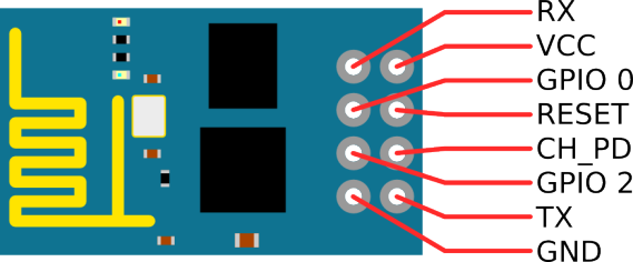
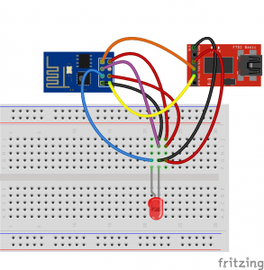
Step 5: Pin Conncetion for ESP8266 to USB-TTL Converter
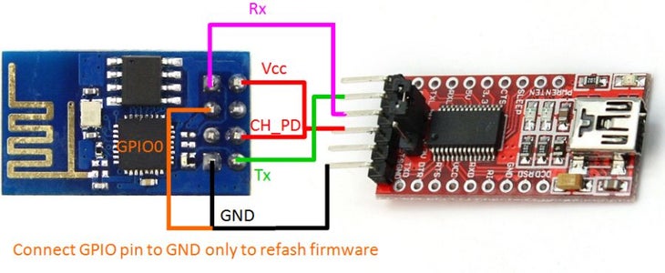

Here are connection details for ESP8266 to USB-TTL Converter
- Connect USB-TTL 3.3V to ESP8266 VCC & CH_PD
- Connect ESP8266 RX to USB-TTL TX & ESP8266 TX to USB-TTL RX
- Connect ESP8266 GND to USB-TTL GND
- Connect LED to GPIO 2 & GND
- Connect GPIO 0 to GND (ONLY DURING SKETCH UPLOADING)
Step 6: Code Uploading and Program
Plug the USB-TTL to your System & select the port at Tools > Ports > COMn (Ex-COM4)
Now, edit the details like- WiFi Name, WiFi Password, Domain name, path and compile the sketch & upload to ESP8266.
If you have server then you can use your own by php and json code you can download the source file by the below link, else you can use my uploaded code http://www.bipulgupta.com/IoT/
For any issue you can contact me-
Bipul Kumar Gupta
Attachments


Participated in the
Wireless Contest

Participated in the
LED Contest 2017

![Tim's Mechanical Spider Leg [LU9685-20CU]](https://content.instructables.com/FFB/5R4I/LVKZ6G6R/FFB5R4ILVKZ6G6R.png?auto=webp&crop=1.2%3A1&frame=1&width=306)


