

Introduction: LEDS With a Potentiometer


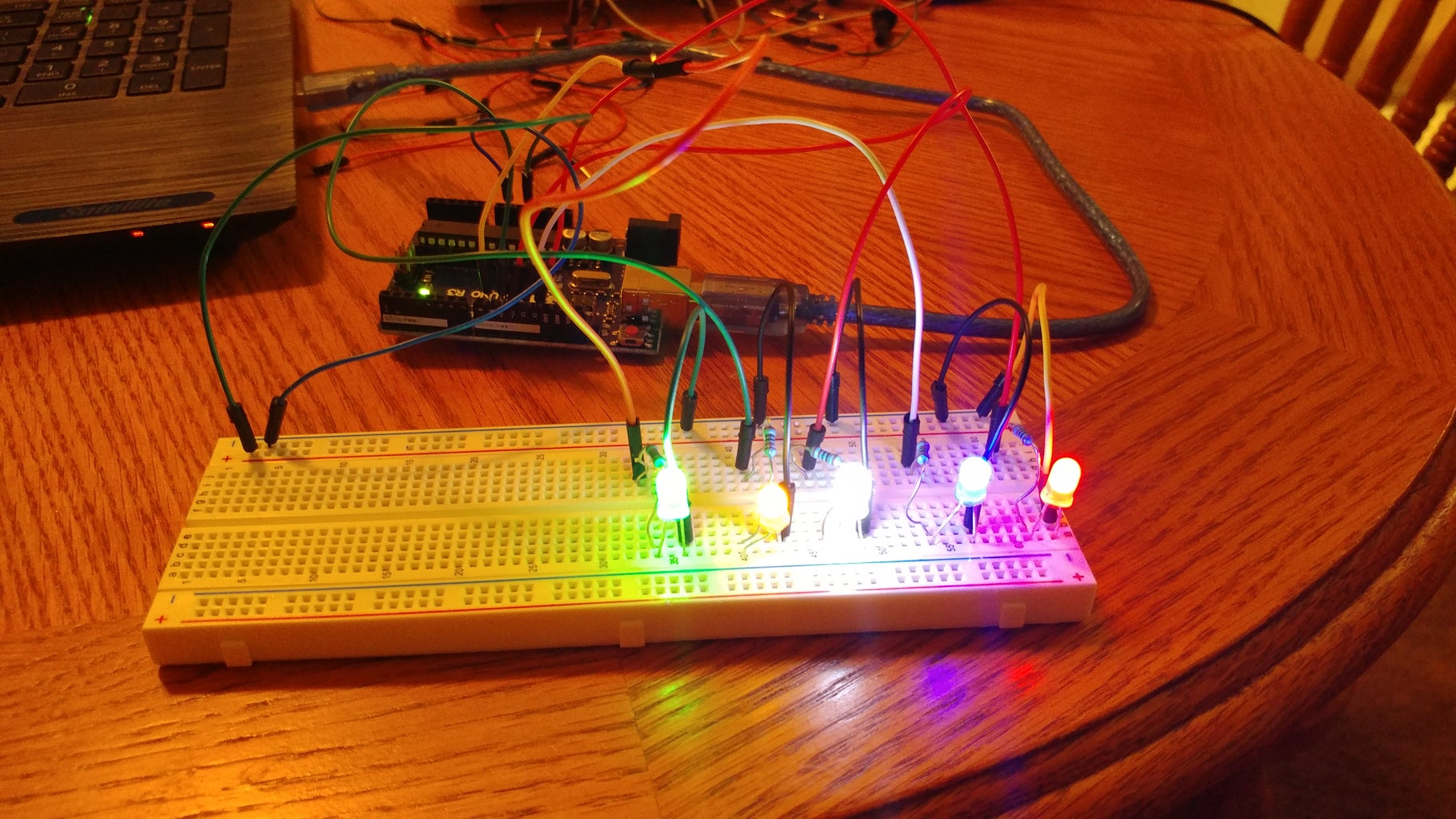
Here we will creating a project that will have 5 LEDS that will be controlled by a Potentiometer. We will be doing a couple of things with it: such as controlling which leds are on with the Potentiometer and making the leds fade.
Materials Needed:
- 1 Breadboard
- 1 Arduino Uno
- 5 LEDS
- 1 Potentiometer
- 15 Wires
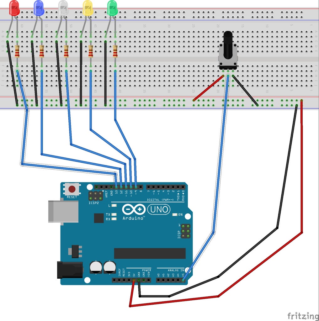
Step 1: Add 5 LEDS


Before we start adding LEDS, we need to remember to wire the Arduino Uno to the breadboard
- Connect a wire from the 5V pin to the power side (red) of the breadboard
- Next, run a wire from one of the GND pins to the negative side (blue) of the power rail
Now that we have grounded and have power to our breadboard, we can add the LEDS
- Add 5 LEDS in a row at the back of the breadboard
- Run a wire from the Negative prong(its shorter) to the grounding rail on the breadboard
- Put one end of a 220 Resistor right in front of the Positive lead. Hook the other end into one of the holes in front of it. This will insure our LEDS don't fry.
- Take a wire from the hole right in front of the end of the Resistor and connect it to a Pin in the Arduino. For my 5 LEDS, I used PINS 11, 10, 9, 6, and 3. Its importent to use these pins cause these are PWM pins and will be needed later in the step.
- Repeat these steps for each of the LEDS
Now I've learned the hard way to test your code and components as you go, so lets write out the code to turn all the leds on.
<p>int redLED = 13; //Pin numbers for the LEDS<br>int blueLED = 12;
int whiteLED = 11;
int yellowLED = 10;
int greenLED = 9;</p><p>void setup() {
  // put your setup code here, to run once:
pinMode(redLED, OUTPUT); //Recognize the LEDS as OUTPUT
pinMode(blueLED, OUTPUT);
pinMode(whiteLED, OUTPUT);
pinMode(yellowLED, OUTPUT);
pinMode(greenLED, OUTPUT);
}</p><p>void loop() {
  // put your main code here, to run repeatedly:
  digitalWrite(redLED, HIGH); //Turn all the LEDS on
  digitalWrite(blueLED, HIGH);
  digitalWrite(whiteLED,HIGH);
  digitalWrite(yellowLED, HIGH);
  digitalWrite(greenLED, HIGH);</p>
Step 2: Attach a Potentiometer

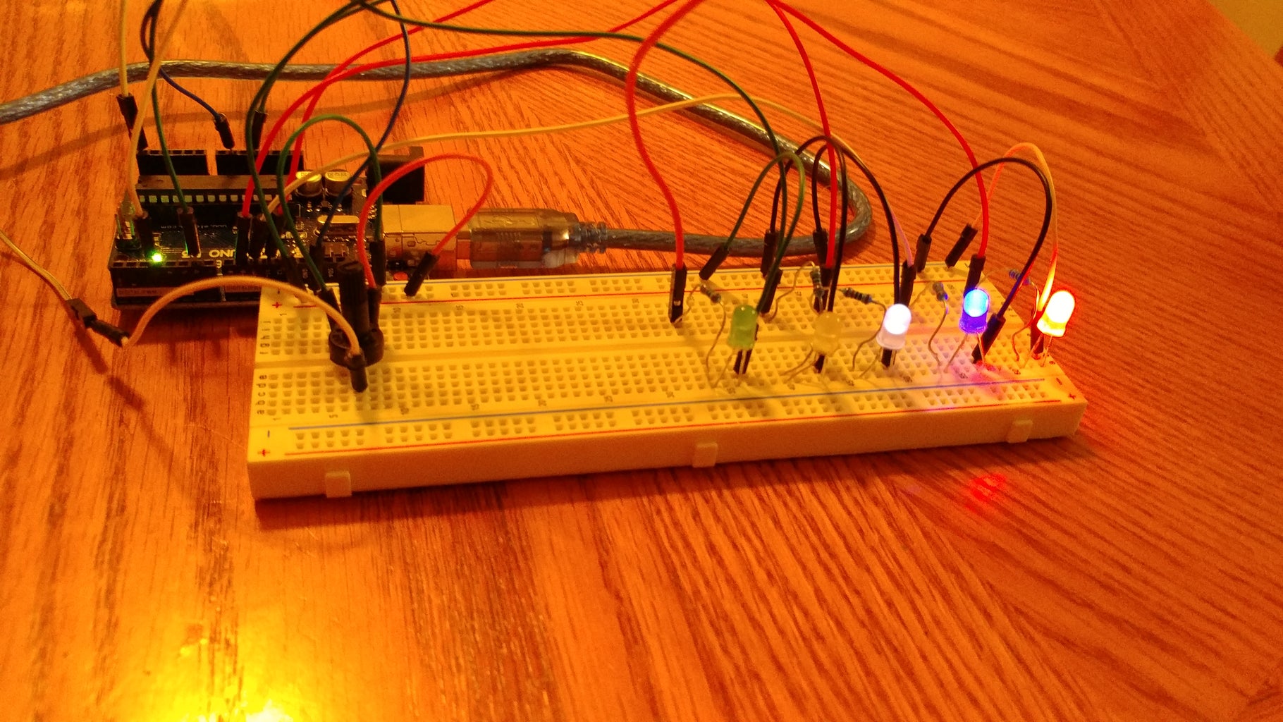
Now lets add the next component: a Potentiometer.
Put the Potentiometer on the opposite side of the breadboard as your LEDS. This will help save space and make it less likely to accidently pull wires out.
- From the front left prong to the power rail, run a wire.
- The front right prong connect a wire to run to the grounding rail.
- On the single prong in the back, run a wire to an Analog Pin. I used A5
Now that we have the Potentiometer wired and connected, lets test it out in the code.
int redLED = 13; //Pin numbers for the LEDS<br>int blueLED = 12;
int whiteLED = 11;
int yellowLED = 10;
int greenLED = 9;
int potent = A5;  //Pin for the Potentiometer
int potentNum = 0; // int to keep track of the values coming from the Potentiometer
void setup() {
  // put your setup code here, to run once:
pinMode(redLED, OUTPUT); //Recognize the LEDS as OUTPUT
pinMode(blueLED, OUTPUT);
pinMode(whiteLED, OUTPUT);
pinMode(yellowLED, OUTPUT);
pinMode(greenLED, OUTPUT);
Serial.begin(9600); //Begin the Serial Moniter
pinMode(potent, INPUT);
}
void loop() {
  // put your main code here, to run repeatedly:
  /*digitalWrite(redLED, HIGH); //Turn all the LEDS on
  digitalWrite(blueLED, HIGH);
  digitalWrite(whiteLED,HIGH);
  digitalWrite(yellowLED, HIGH);
  digitalWrite(greenLED, HIGH);*/
  potentNum = analogRead(potent);    // gets value from sensor
  Serial.println(potentNum);
  delay(300);
}
Step 3: Modify Code to Cycle Through LEDs

Now we have to go into our code and make it so that the Potentiometer controls what LEDs are on. For my code, I went with some coding that I just enjoy using. I put all the LEDs into an array, modified the map function to return a value between 0 and 4. I then used that value in a Switch statement to control what LEDs are turned on and off. There might be easier ways to do it, but I had fun with how I did it.
Code:
int ledArray[] = {13, 12, 11, 10, 9}; //Array of Leds<br>int potent = A5; //Pin for the Potentiometer int potentNum = 0; // int to keep track of the values coming from the Potentiometer
void setup() {
// put your setup code here, to run once:
for(int i = 0; i < 6; i++) //Set all the LEDS as OUTPUTS with a for loop
{
pinMode(ledArray[i], OUTPUT);
}Serial.begin(9600); //Begin the Serial Moniter
pinMode(potent, INPUT); //Declaring the Potentiometer as INPUT }
void loop()
{
// put your main code here, to run repeatedly:
potentNum = analogRead(potent); // gets value from sensor
int num = map(potentNum,0,1023,0,4); //Mapping the Potentiometer sensor data with the Map Funtion. Noticably we are having the
//toLow and toHIGH be from 0 to 4. This lets us switch through the arrays
Serial.println(potentNum);
switch(num) //switch statements to turn LEDs on/off
{
case 0:
digitalWrite(ledArray[0], HIGH);
digitalWrite(ledArray[1], LOW);
digitalWrite(ledArray[2], LOW);
digitalWrite(ledArray[3], LOW);
digitalWrite(ledArray[4], LOW);
break; case 1:
digitalWrite(ledArray[1], HIGH);
digitalWrite(ledArray[0], LOW);
digitalWrite(ledArray[2], LOW);
digitalWrite(ledArray[3], LOW);
digitalWrite(ledArray[4], LOW);
break; case 2:
digitalWrite(ledArray[2], HIGH);
digitalWrite(ledArray[0], LOW);
digitalWrite(ledArray[1], LOW);
digitalWrite(ledArray[3], LOW);
digitalWrite(ledArray[4], LOW);
break; case 3:
digitalWrite(ledArray[3], HIGH);
digitalWrite(ledArray[0], LOW);
digitalWrite(ledArray[1], LOW);
digitalWrite(ledArray[2], LOW);
digitalWrite(ledArray[4], LOW);
break; case 4:
digitalWrite(ledArray[4], HIGH);
digitalWrite(ledArray[0], LOW);
digitalWrite(ledArray[1], LOW);
digitalWrite(ledArray[2], LOW);
digitalWrite(ledArray[3], LOW);
break;
}
delay(300);}
Step 4: Fade LEDS As Potentiometer Turns
Now we are going to fade the leds with the Potentiometer instead of just having them turned on and off. We will be changing the code quite a bit. We are changing the setup of the leds from pinMode to analogWrite. In the switch statments we will also be swapping out digitalWrite for AnalogWrite anding our desired brightness to the leds. We will also streamline the case statements for clarity
Code:
int ledArray[] = {11, 10, 9, 6, 3}; //Array of Leds
int potent = A5;  //Pin for the Potentiometer
int potentNum = 0; // int to keep track of the values coming from the Potentiometer
void setup() {
// put your setup code here, to run once:
for(int i = 0; i < 6; i++) //Set all the LEDS as OUTPUTS with a for loop
{
analogWrite(ledArray[i], 2);
}Serial.begin(9600); //Begin the Serial Moniter
pinMode(potent, INPUT); //Declaring the Potentiometer as INPUT
}
void loop()
{
  // put your main code here, to run repeatedly:

  potentNum = analogRead(potent);    // gets value from sensor
  int num = map(potentNum,0,1023,0,4);  //Mapping the Potentiometer sensor data with the Map Funtion. Noticably we are having the
                                        //toLow and toHIGH be from 0 to 4. This lets us switch through the arrays
//int brightness = map(potentNum, 0, 1023, 0,255);
//Serial.println(brightness);
switch(num) //switch statements to turn LEDs on/off
{
case 0:
analogWrite(ledArray[0], 255);
analogWrite(ledArray[1], 10);
analogWrite(ledArray[2], 1);
analogWrite(ledArray[3], 0);
analogWrite(ledArray[4], 0);
break; case 1:
analogWrite(ledArray[0], 10);
analogWrite(ledArray[0], 255);
analogWrite(ledArray[2], 10);
analogWrite(ledArray[3], 1);
analogWrite(ledArray[4], 0);
break; case 2:
analogWrite(ledArray[0], 1);
analogWrite(ledArray[1], 10);
analogWrite(ledArray[2], 255);
analogWrite(ledArray[3], 10);
analogWrite(ledArray[4], 1);
break; case 3:
analogWrite(ledArray[0], 0);
analogWrite(ledArray[1], 1);
analogWrite(ledArray[2], 10);
analogWrite(ledArray[3], 255);
analogWrite(ledArray[4], 10);
break; case 4:
analogWrite(ledArray[0], 0);
analogWrite(ledArray[1], 0);
analogWrite(ledArray[2], 1);
analogWrite(ledArray[3], 10);
analogWrite(ledArray[4], 255);
break;
}
delay(300);}
And thats it! Thank you for looking at my Instructable.
