

Introduction: Lesson 4: Basic Arduino Pt. 2: Introduction to Coding


Welcome back, eager learners. For those new to this series, please see my previous lessons in basic electrical engineering. For those not new, prepare to enter the world of coding, where you can manipulate how your circuit behaves through a computer. This is where hardware meets software!
*Hardware being the physical circuit
**Software being the code controlling the circuit.
Step 1: What Is Code?
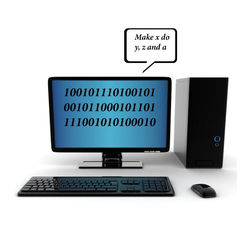
Now, suppose you aren't exactly good with computers, how should you visualize code? Imagine this. Many years ago, brilliant scientists devised a way to communicate with computers in zeros and ones. Patterns in zeros and ones allowed us to tell computers to do certain things. As shown on the image, the display of zeros and ones, to the computer, mean "I want you to do this and that!"
Nowadays, we have found much more efficient ways of telling computers to do what we want without using just 0s and 1s. These are coding languages, where you type in a few key phrases (in english of course), and the computer translates it into the numbers it can understand. But how can we see this powerful technique seen in action? Enter Arduino...Again!!!
Step 2: Arduino Can Be More

Last time you saw arduino, I discussed how you could use it as a power source. Now I will show you how to control it using the power of code!
The project you will be doing is to use an arduino to make an LED blink. Wait? What? From what I've told you, no electronic device can just be put in a circuit and make the LED blink! Right? Well, no, actually! But how can we use this blue, and til this point, opaque chip to do something that we could not do ourselves?
Step 3: Designing the Circuit

Regardless of how you will make your LED blink, you will still need a physical circuit. The materials you will need are an arduino uno, a power source and a USB that you will need to give arduino code.
To construct your circuit all you will need is an LED and an Arduino Uno. In the image, you see the LED's long leg is attached to the pin labeled "13". Then, you may notice that the short leg of the LED is attached to the pin labeled "gnd". Those who saw the previous lesson should know that this is ground. But you may be wondering, "Hey, this is no complete circuit! Where's the power! This will never turn on a LED!"
Remember, although that is correct, we never gave any code to tell the LED to turn on. So when attaching the LED to pin 13 and ground, and then attach an Arduino to it, it should not blink*. Do not worry about inserting a resistor into the circuit. The ground that the LED is attached to has a resistor built into it, so no short circuits will occur.
* When attaching a power source to the arduino, the LED will blink, but only because the arduino is buffering. A few seconds after, the LED will turn off, unless blinking is in the code.
Step 4: When Opening Arduino
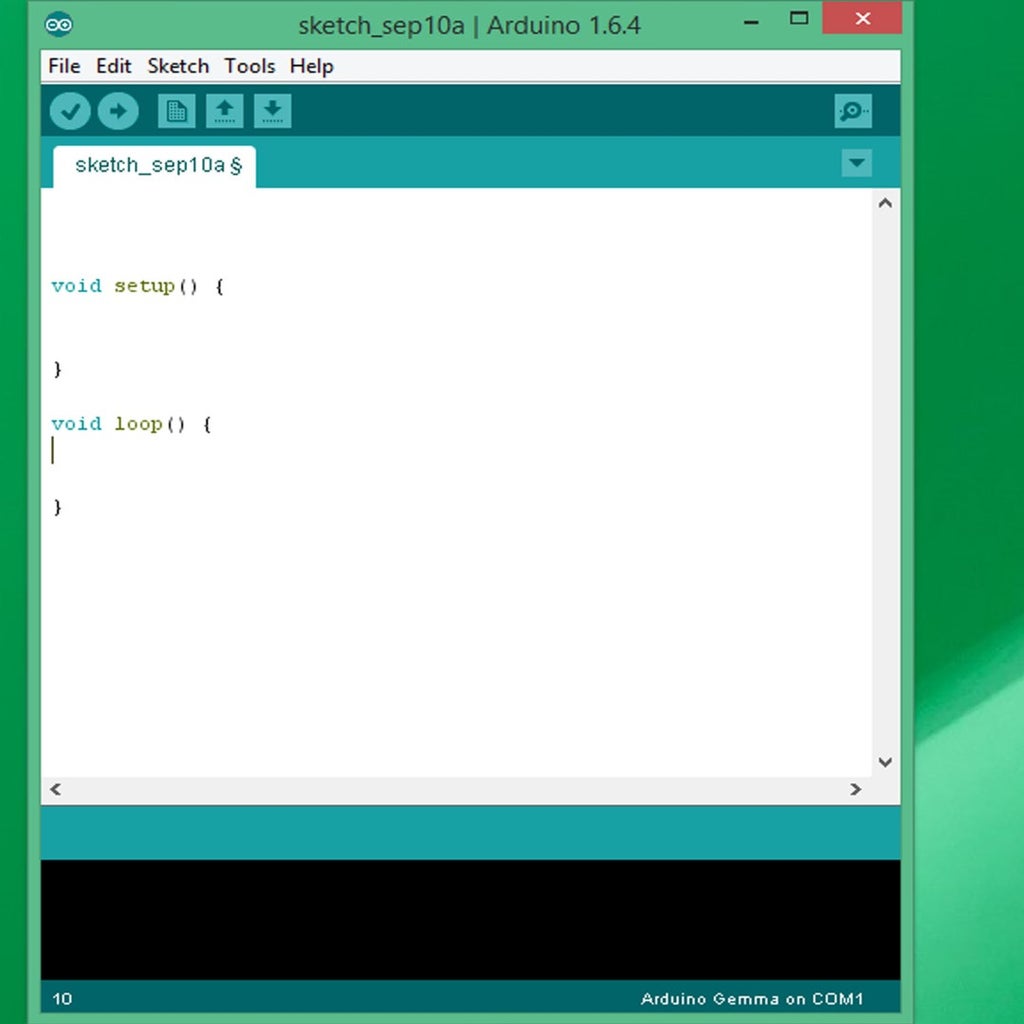
Assuming you have downloaded the Arduino app's newest update (version 1.6.4, for those interested), you should get a window that looks like the image displayed when you open it.
What it should read is void setup() and void loop(), each with a pair of curly brackets ({ }). Between each pair of those brackets, certain pieces of code will be written. But first, before we tell the computer what to do, we want to let the computer know what part of the arduino we want to control.
Step 5: Defining the Pin of Control
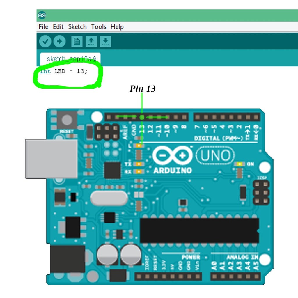
When telling a computer that you want to control a pin, first you have to define the pin as an integer, seen in the first picture. Above the void loop and setup, write int LED = 13; What this does is say that there is a piece of data whose value equals 13. When ending a line of code, end it with a semicolon. That is the arduino code format.
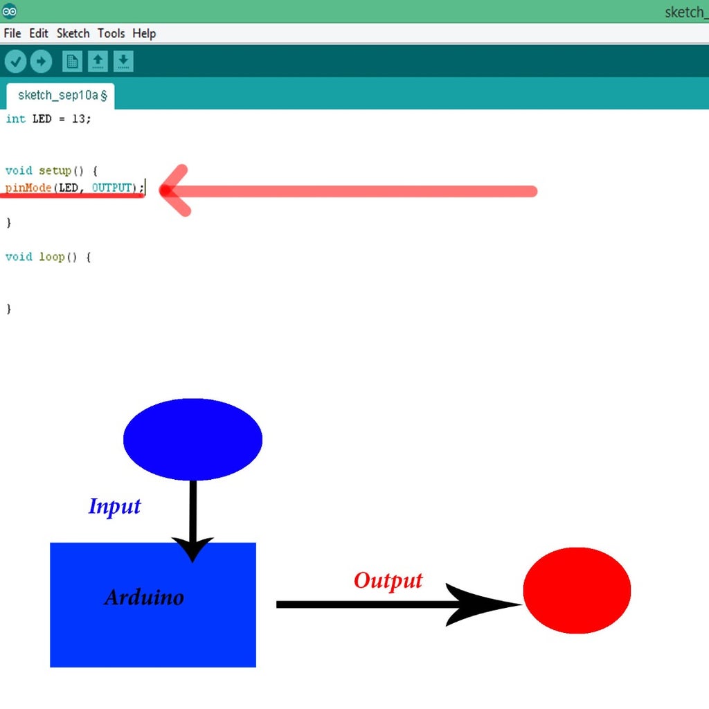
The next step of defining your LED pin in the code is to say that it is a pin. To do this, in between the brackets of void setup(), write pinMode(LED, OUTPUT);Writing "pinMode" triggers the computer to think that whatever variable you put in the parentheses, it will associate that variable's value to a pin. So now what we have done is initialize the fact that LED is a pin on the actual arduino uno. The second part of the parentheses, where it says "OUTPUT", determines whether or not you are going to give data to the pin or get data from the pin. If it is OUTPUT, then the arduino will only give information to the pin. If it is INPUT, then the pin will be giving the Arduino information. This concept is shown on the diagram of the second image.
Since it says OUTPUT inside the pinMode parentheses, we know that whatever code we write in the loop, we will be telling the LED to do something. Now that we established to the computer that LED is an actual pin, lets tell the computer what to make the LED do.
Step 6: Writing Commands

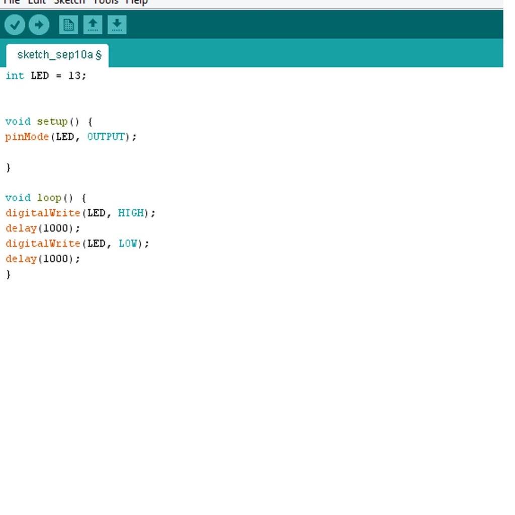
To start writing your commands, go in between the brackets under void loop(). For this example, write the new code seen in the first above image. What you should write is digitalWrite(LED, HIGH); What this statement does is tell the arduino to turn on pin LED (or pin 13). DigitalWrite is what you use to say to turn something on or off, as explained in the first diagram. Next, write a second line, which goes like delay(1000); What this statement allows is for you to control how long you want the LED to be on. What ever value you put in the brackets is the number of milliseconds that the action will be done, so the LED will be on for one second.
Of course, since you never told the LED to be off anywhere in the code, you have to add a second pair of lines. To do this, duplicate the two lines that you just wrote and place them below. Keep the delay the same, but change the HIGH to a LOW. What this does is tell the arduino to turn off the LED. Now your code is done! The code you wrote should look like the completed version you see in the second image. Reffer to this if there is any difference between your code and this!
Now that you have the code to tell your LED to blink, how do you upload it?
Step 7: Upload Your Code


When you upload your code to your arduino, make sure you have a USB hooked up to your arduino. Next, check to see that your computer knows what kind of arduino it is 'talking' to. To do this, go to the tab on the window labeld "tools". When you click on it, look down the menu and make sure you see "board Arduino Uno", as seen in the first image.
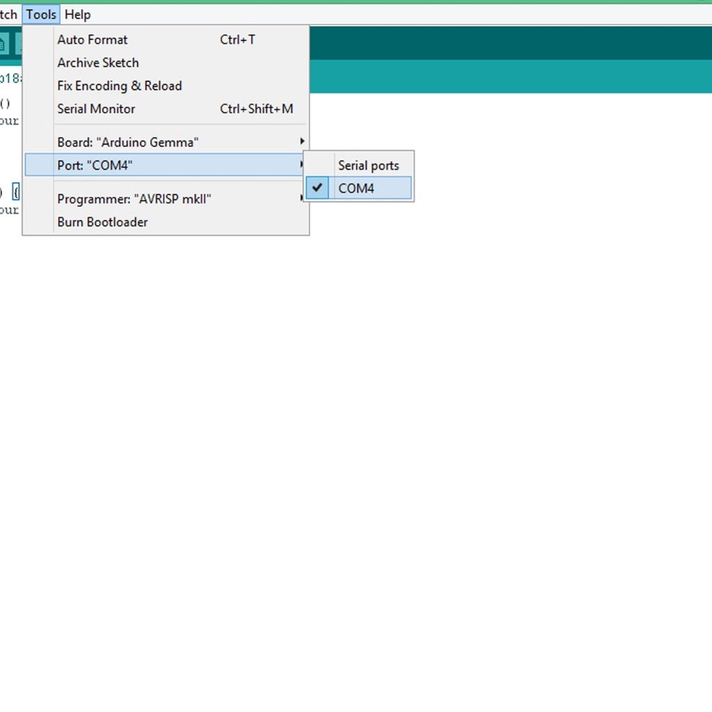
Next, click on the tab of the window labeled "tools", as seen in the second image. A menu should drop down. Hover over "port" and a list of numbers should come from that. Each number represents a USB you have attached to the computer that can upload code into arduios of all sorts. Click on the appropriate number associated with the USB you are using for your arduino. A check mark should be next too it, as seen in the second image.
After you are done, click on the highlighted button in the third image. This will upload your code into your arduino! While the code is being uploaded, you may see the LED blink a little, but this is not part of the code. After the arduino receives the code, the LED should start blinking! One second on, one second off. Congradulations! You have made your first arduino-based program!
Step 8: Hierarchy of Electronics

Now you see the power of coding over the real world. A simple set of commands given to a small blue chip has the power to affect how electronics behave! Code controls arduino, which controls the LED. Now isn't that wizard!
Hopefully, you learned the basic vocabulary of arduino and how it translates into the real world. More importanly, I hope you learn how powerful coding can be when used properly. The idea of what you want to do, stated through a computer, can alter your sorroundings! In the world of coding, it is mind over matter! I hope you enjoyed this lesson, and learned a couple new tricks!
NEXT TIME...
Next time, we will look into what a sensor is how we could properly use them to gather information from the environment! *bad pun alert**bad pun alert*This subject will be a very sensitive one!


