

Introduction: LiFi Communication

In this instructable you will learn how to implement LiFi communication (transmitter and receiver) on a software and hardware level.
Step 1: Gather Components

Things you will need:
-Arduino and Zedboard
-oscilloscope
-Resistors: 8k ohm, 1k2 ohm, 1k ohm, 220 ohm and 27 ohm.
-opamp, capacitor, zenerdiode, photodiode, LEDs and breadbord.
Step 2: Building the Design


On the image, the schematic for the receiver is given.
First, connect the anode (negative terminal) of the photodiode to 3.3V (Vcc), the cathode (positive terminal) to ground through a 8k2 ohm resistor. Also connect the cathode to the positive terminal of your opamp, which will be used to amplify the signal. We are using negative feedback so connect 2 resistors to the negative terminal of the opamp, 1 (1k2 ohm) goes to the output of the opamp, the other (220 ohm) goes to ground. To protect your GPIO pin, connect a reversed biased zener diode of 3.3V in series with a 1k2 ohm resistor to ground. The output of the opamp needs to be connected to a GPIO pin.
The transmitter just consists of one 27 ohm resistor and a LED in series. One end goes to a GPIOpin and the other to ground, making sure that the short leg of the LED is connected to ground.
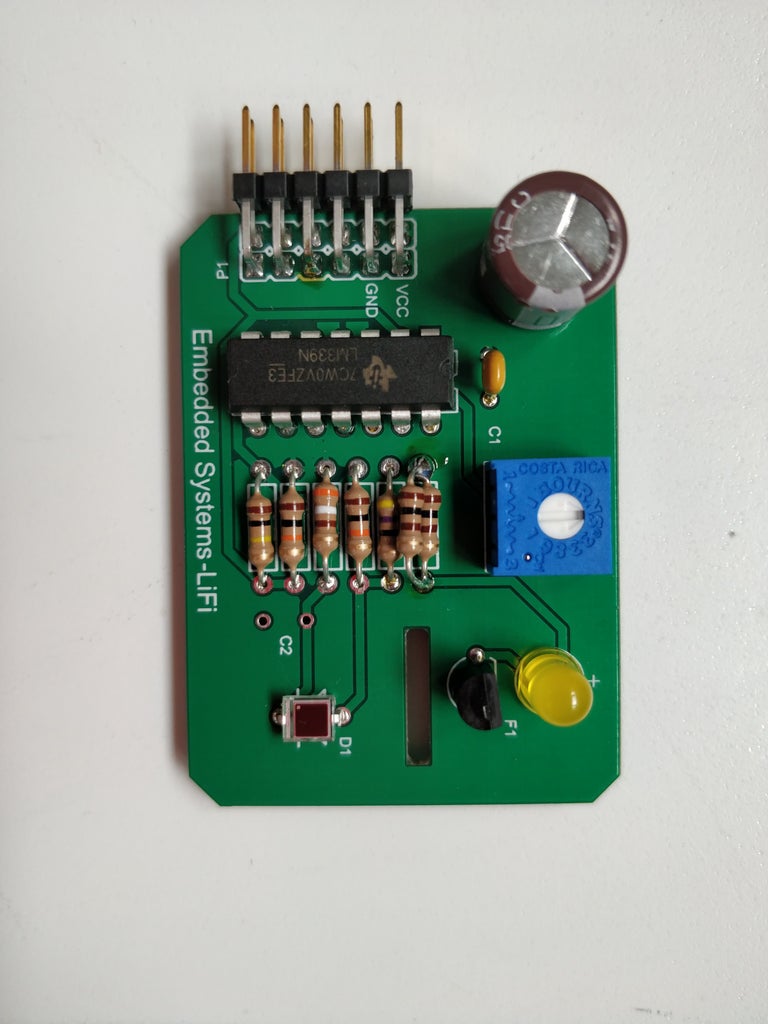
If the designs are working you can make a PCB for it. On the PCB we combined the transmitter and receiver on one board, so we can eventually send data in two directions. You can also see the PCB schematics in the images for the receiver and transmitter.
Step 3: Testing the Design
Use an oscilloscope to check the design because ambient light and the difference in photo diodes can give different results in output signal.
Connect your transmitter to an arduino and generate a square wave with the desired frequency. Put the transmitter LED close to the photo diode.
Connect one probe to the positive terminal of your opamp, another to the output of your opamp. If your output signal is too weak the negative feedback resistors (1k2 ohm, 220 ohm) need to be changed. You have 2 choices, increase the 1k2 ohm resistor or decrease the 220 ohm resistor. If the output is too high, do the opposite.
If everything looks ok, proceed to the next step.
Step 4: Getting All the Necessary Software

On the image the different encoding steps can be seen to implement LiFi. To decode, the same steps need to executed in reverse.
For this project some libraries are needed, they are included in the given files and here are the links to the github repository:
-Reed-Solomon: https://github.com/ArashPartow/schifra
-Convolutional encoder: https://github.com/xukmin/viterbi
To get the files to do what we want, we made some adjustments in them so it is necessary to use our version of the libraries, included in the files.
After the convolutional encoder, one last encoding step is needed, the manchester encoding. The data from the convolutional encoder is send to a fifo buffer. This buffer is read in the PL part of the zedboard, the project is included in the 'LIFI.7z' file. With the project you can built your own bitstream for the zedboard or you can just use the bitstream we provided. To use this bitstream you have to install Xillinux 2.0 on the zedboard first. The explanation how to do this is provided on the Xillybus website.

Step 5: Make the Executables
Two separate executables need to be made, one for the transmitter and one for the receiver. To do so, the following commands need to be executed on the zedboard:
- Transmitter: g++ ReedSolomon.cpp Interleaver.cpp viterbi.cpp Transmission.cpp -o Transmitter
- Receiver: g++ ReedSolomon.cpp Interleaver.cpp viterbi.cpp Receiver.cpp -o Receiver
Step 6: Testing Everything
Connect the transmitter to the JD1_P pin and the receiver to the the JD1_N pin on the zedboard. Make sure to change the constraint file if you wish to change the standard pins.
To test if everything works, open 2 terminal windows in the PS part. In one terminal execute the receiving part first. After that, execute the transmitter part in the second terminal window.
If everything goes as it should, the result should be the same as on the image above.

![Tim's Mechanical Spider Leg [LU9685-20CU]](https://content.instructables.com/FFB/5R4I/LVKZ6G6R/FFB5R4ILVKZ6G6R.png?auto=webp&crop=1.2%3A1&frame=1&width=306)


