

Introduction: LinkIt One Tutorials - #5 Grove Headers


One of the less obvious extras on the LinkIt One board are two white headers with 4 pins in. These are called Grove headers and are designed so that you can attach a wire and be able to use all types of hardware simply and easily.
For this tutorial I will be installing the Grove libraries for Arduino and showing just how easy it is to use Grove compatible hardware.
Step 1: Materials Required


I bet you're getting bored of the quips now so no more from this point on. I will happily retrofit quips should you want it (people power!), just ask in the comments section.
LinkIt One board
Micro USB cable
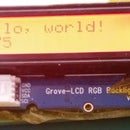
Grove LCD RGB Backlight
I got mine from seeedstudio.com who have lots of great bits of kit to play with.
http://www.seeedstudio.com/depot/Grove-LCD-RGB-Backlight-p-1643.html
Grove connector wire
Again I got mine from seeedstudio.com http://www.seeedstudio.com/depot/Grove-Universal-4-Pin-Buckled-20cm-Cable-5-PCs-pack-p-936.html
Arduino IDE
Grove LCD RGB library
Download from https://github.com/Seeed-Studio/Grove_LCD_RGB_Back... - specifically you want the file https://github.com/Seeed-Studio/Grove_LCD_RGB_Back... which is a small (22KB) file that contains the libraries and example code.
Step 2: Add New Library to the Arduino IDE


At one time Arduino library installation used to be a really painful process. Now (thankfully) it is just a matter of a few clicks to install a library from a zip file.
If you know how I recommend you change the filename of the zip from Grove_LCD_RGB_Backlight-master.zip to Grove_LCD_RGB_Backlight.zip - remove the -master. It is not essential to do this but I prefer it without the -master.
Click on the Sketch menu, Include Library, Add .ZIP Library...
In the new window that opens, browse to wherever you downloaded the zip file from step 2 and click on it. Now click the Open button at the bottom right.
The Arduino IDE has a blue bar at the bottom which gives the status of whatever you have done. It should read
Library added to your libraries. Check "Include Library" menu
If it does, excellent, you are now ready to play with one piece of Grove hardware, the Grove-LCD RGB Backlight.
I really like this piece of kit as it has a 16x2 LCD display and the backlight can be any of 16 million colours.
Step 3: Load the Grove LCD Hello World Program Into the IDE


Flashing an LED to say "Hello World" is brilliant but we want more from our toys, don't we?
Remember all those 1960s films that showed computers as monolithic beasts covered in blinking lights? How were you ever supposed to know which light meant "hello world" and which meant "I am overheating and about to explode"?
How about displaying the words "hello, world!" so they can be read instead?
If your board is connected via USB unplug the USB cable and plug one end of the Grove Connector cable into the Grove Header socket on the LCD display.
Note that the text next to the connector reads "GND VCC SDA SCL".
Examine the LinkIt One board and look at the two Grove Header socket.
One has text that reads "RX TX 5V GND" and the other "SCL SDA 5V GND".
Plug the free end of the Grove Connector cable into the Grove Header socket that reads "SCL SDA 5V GND".
Reconnect the USB cable and look at the Grove LCD RGB.
There should be a line of black squares on the top row. This is the universal "Hello World" for LCD displays when first powered up.
In the Arduino IDE click on File, Examples, Grove_LCD_RGB_Backlight-master, HelloWorld (see why I recommended removing -master earlier?)
Ensure the serial port has appeared in Tools-Port. If it has not appeared, wait a few seconds and try again.
Click Sketch, Upload and wait until it finishes.
Have a look at your Grove LCD RGB Backlight, it should have a light red backlight and "hello, world!" with a counter climbing up on the second line. The counter is how many seconds the program has been running for.
Step 4: Where Next?

Now we have a simple way of getting textual information from the LinkIt One we can really start to expand.
I am going to be using the battery in the next tutorial so you may wish to connect that to the board to allow it time to charge up.
Be sure to unplug the LinkIt One from the USB cable before inserting the battery.
If you are unsure how to connect the battery, leave it and I will give instructions in my next tutorial.

![Tim's Mechanical Spider Leg [LU9685-20CU]](https://content.instructables.com/FFB/5R4I/LVKZ6G6R/FFB5R4ILVKZ6G6R.png?auto=webp&crop=1.2%3A1&frame=1&width=306)


