

Introduction: MOTORIZED CAMERA SLIDER With TRACKING SYSTEM (3D Printed)


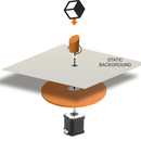
Basically, this robot will move a camera/smartphone on a rail and “track” an object. The target object location is already known by the robot. The math behind this tracking system is quite simple. We have created a simulation of the tracking process here.
The camera, placed on a carriage as it moves, will point at the target object according to the info provided to the robot (that is: the target current location. Keep in mind that the robot already knows where the camera is).
The speed and start/stop actions are controlled from your own smartphone. For this, the smartphone has to be connected to the robot´s WIFI network.
As the speed can be adjusted as desired (from the smartphone), you can move the “camera carriage” as slow as desired, making possible to create TIME LAPSE videos.
Control APP freely available on Google PLAY or iTunes Store
Supplies
Useful LINKS:
Step 1: PARTs LIST


We have used common elements from the DIY/MAKER World in order to make this robot accessible and affordable.
Parts list:
3D printed parts SET
MOTOR CABLE (70 cms)
MOTOR CABLE (14 cms)
16 teeth GT2 pulley
20 teeth GT2 pulley
Circular Ball bearing 6002RS or 6002ZZ
Timing belt GT2 (150cm for a 700mm rail) + 200mm GT2 ring belt
USB cable 1m (micro USB connector)
Camera Swivel
Anodized Aluminum profile (2020 V-shape)
3x Wheel bearing (V-shape)
Smartphone holder + camera screw (short)
12V/2A Power supply with 2.1mm POWER JACK
M3 bolts (10mm,15mm and 20mm) + nutsM5 25mm bolts
Electronics:
- DEVIA Robotics Control Board
- 2x TMC2208 Ultra Silent motor driver + aluminium heatsinks (long version)
- 2x NEMA 17 high torque stepper motors + 14 cms cms + long cable (70 cms)
- Micro-USB cable
You can get everything on your own (most of the elements are the same used in the B-robot, iboardbot,sphere-o-bot, Scara Robotic arm, Air hockey Robot...) or save the hassle ordering the CUSTOMIZABLE KIT from our shop (and at the same time you will be supporting jjRobots):
GET THE CAMERA SLIDER PARTS from jjRobots (Customizable KIT)
Step 2: 3D Printing All the Parts. Printing Time: 10-14 Hours (depending on the 3Dprinter)

PLA will do the job. When printing, set the wall thickness= 1.2 mm and infill to at least 25%.
All the 3D parts models are available at Thingiverse
Step 3: Assembling
Basically, this is a rail with a platform that will travel on it controlled by an Arduino + 2 NEMA17 stepper motors. The two motors will be in charge of: 1) move back and forward the camera platform 2) pan the camera as it moves on the rail. The GOPRO/Smartphone adapter is optional, so you do not have to 3D print it if you are planning to use a regular photo camera. The total length of the rail can be modifiable. To up to 2 meter, the robot behaves smoothly, over that length and for a camera of more than 500 grams (1.1 pounds) the rail might bend under the weight while the camera cross the middle of the rail.
This is the robot 3D model. Click on PLAY a take a 3D look at it. Get back to this model if you have doubts about where to place an element.
The Latest assembly guide: UPDATED
BEFORE STARTING: Most of this Camera slider KIT´s elements have been "3D printed". Keeping this in mind: You can break it if you apply too much force or tight a screw more that you should. We will let you know, during this assembly guide, when you can tighten the screws as much as you can or where you should just fix a part to another not forcing it at all.

Insert the M5 25mm bolts + Wheel bearing into their sockets as indicated below. Do not over-tighten the bolts.

This is how it should look. Check if there is burr on the 3D printed parts if you feel friction when spinning the wheels.

Insert one M3 nut and capture it using a 16mm M3 bolt. This bolt will let you adjust the distance between the wheels in the case there is some tolerance discrepancy after printing the parts. Adjust it only when the carriage has been placed on the aluminum rail.

Place the TOP part on top of the BOTTOM part and use 4x M3 10 mm bolts to fix it. Insert the 6002RS ball bearing as indicated above. IMPORTANT: The 6002RS has to be tight. You can even glue it to its support if you feel it is loose.

This is the moment to adjust the bolt in the carriage with the idea of making it stable. Move it back and forth: all the wheels should be spinning but you should not feel resistance or hear any noise. Force the carriage and check if all the wheels are kept inside the aluminum rail channels.

Insert the 3D printed "PULLEY 80 teeth" as above. Capture it with the CAP and a M3 10mm bolt. The same goes for the pulley: it has to be tight around the 6002RS ball bearing. Glue it to the ball bearing if that is not the case.

- Place the motor as indicated and hold it using 4x M3 6mm bolts (but let them loose)
- Place the 16 teeth pulley on its shaft and, at the same time, run the 200mm GT2 belt around the pulley
- When everything has been set, push the motor "back" so the belt gets tense. Once there, screw the bolts fixing the motor position.

Top view of the carriage at this point. Check the orientation of the motor’s connector.

Bottom view of the carriage.

Now take the camera screw and the "SCREW CAPTURING RING" and do as above. The screw´s head will stay in place thanks to this 3D printed part. Now you can attach the PULLEY TOP to the SCREW CAPTURING RING using 4x M3 10mm bolts

If you want more flexibility when pointing the camera, use the camera´s swivel. It will let you adjust the camera tilt / orientation easily

This is how the carriage looks on the rail. We still have to run the timing belt. Check the steps below

Fix the NEMA17 motor to the MOTOR END part and fix it using 4x M3 15mm bolts.

Attach and fix the 20 teeth pulley to the shaft. The top of the shaft has to be levelled with the pulley.

Use 2x M3 10mm bolts to join the PULLEY END LEGS to the PULLEY END

Push the PULLEY END into the aluminium profile. You may need the mallet (or equivalent). Take out, temporarily, the pulley if you think you can damage it, in the process. At this point, do not fully insert the aluminum profile into the PULLEY END.

Run the timing belt around the pulley and back to the aluminum profile. Now it is time to push the PULLEY END completely (make use of the mallet). Be gentle!

Capture the timing belt end as indicated. You may need to use pliers at this point. Push the belt to the very end so it is fully inserted, otherwise it will touch the rails when the carriage is moving back and forth. Insert a nut and 10mmbolt as in the photo. That bolt, will keep the belt in place.

Check that the belt is coming out freely. Any friction here between the belt and the aluminum rail will compromise the stability of the carriage.

Pass it around the 20 teeth pulley as the image and use the mallet to fully insert the MOTOR END part into the aluminum pulley.
NOTE: Do not pay attention to the electronics already placed. That will come later.

Now: pass the belt through its channel. Bend the tip of the belt upwards a little. That will help you to "embellish" it into the "capturing channel"
Tighten the belt, and at the same time, fully screw the bolt. Cut the remaining timing belt

Time to place the electronics. Check the next photo as well, it shows how to put the electronic’s case. Use 1x M3 10mm bolt for the back side of the DEVIA control board (the one I am pointing to). Screw it as shown, that will fix the protective case to the PCB.

Now, flip the board and place it as the image, then attach it to the MOTOR END part using a 10mm bolt (upper left corner hole of the board) and 20mm bolt for the other hole, the one that goes through the protecting case. Two bolts will fix the control board to the MOTOR END piece. Use two M3x10mm to attach the MOTOR LEGS to the MOTOR END.

NOTE: you may need to adjust the output current delivered by the TMC motor drivers. Do that before placing the heatsinks. More info at the very end of this page
Place the heatsinks on top and insert the stepper motor drivers in their sockets. The heatsinks are quite bulky, so this is important: Do not touch the metal headers of the top face of the steppers with the heatsinks. That might create a short circuit damaging the module.
Check the correct orientation of the stepper motor drivers and motor cables.
This is how everything is connected. Check the stepper motor drivers and cable’s connectors orientation (twice!)


Detail: The TMC2208 motor drivers already connected.

Now connect the RAIL MOTOR to the control board. Use the 14cm cable

Do the same with the PLATFORM MOTOR. Use 2 zip ties to fix the cable to the MOTOR END part as the photo. That will keep the cable away from the moving carriage.
NOTE: this step is important, "capturing" the cables will protect the motors headers from being pulled off.

NOTE: The photo shows the camera slider attached to a tripod. You can easily do that with this 3D modelled part + 2xM3 15mm bolts + 2 M3 Nuts. Every tripod has its own fixing system. This 3D part has been created for a standard camera screw 1/4"-20 but you may need to create yours.
Camera swivel and smartphone holder
A helping element of the KIT is the smartphone holder, you can attach it to the popping-out camera screw. Alternatively, fixing that holder to camera swivel, will allow you to tilt the smartphone to any point of interest easier.
HOW TO UPLOAD the ARDUINO CODE to the DEVIA CONTROL BOARD
NOTE:The jjRobots KIT comes with the DEVIA Control Board already programmed, so you can skip this step if you got it.
a) Install the Arduino IDE on your PC from here (skip this step if you have the Arduino IDE already installed)This code has been tested and developed on IDE version 1.6.5 and later versions. If you have a problem compiling the code, let us know
b) Download all the arduino files , extract the files inside the same folder in your hard drive
c) Compile and send the code to the DEVIA control board:
- Open your Arduino IDE
- Open the main code in \CameraSlider_vX_M0 \CameraSlider_vX_M0.ino
- Connect your DEVIA board with the USB cable to the PC
- Note: If this is the first time you connect an Arduino board to your PC maybe you might need to install the driver.
- Select the board Arduino/Genuino ZERO (native USB port). In the TOOLS menu->board (You might need to install the "Arduino SAMD Boards (32-bits ARM Cortex-M0+)" libraries. Go to Tools->Board->Boards Manager… and install the "Arduino SAMD Boards (32-bits ARM Cortex-M0+)"
- Select the serial port that appears on the tools->Serial port
- Send the code to the board (UPLOAD button: Arrow pointing to the RIGHT)

 Selecting the right board before uploading the code
 d) Done!

IMPORTANT: The TMC2208 stepper motor driversare top-notch electronic modules, but they might need to be adjusted to deliver the correct amount of current to the motors. Too much current will overheat the motors. We strongly recommend adjusting the current output to 0.7 A per motor. But how to do that? This wiki provides very good information about it
IF YOU GOT THE CAMERA SLIDER KIT FROM US, the TMC2208 stepper motor drivers are already adjusted. So there is not need to tinker with them ;-)
 Place the stepper motor driver in their sockets on the DEVIA control board and connect the 12V power supply to the board. Measure the voltage between the indicated points above. Use the screw provided with the KIT or get a tiny one (3mm wide). Rotate, anticlockwise, the screw of the potentiometer just a little and check the voltage. Once the voltage has been set to 0.8-0.9 V you are done and the stepper motor drivers are ready to move the camera slider not wasting power as heat.
RMS Current (A): 0.7 <- This is what we want
Reference Voltage (Vref): 0.9V
But... I do not have a multimeter! How am I suppose to do this?. Why did you not send the stepper motor drivers already adjusted?
With the KIT, we supply a tiny screwdriver. With it, just rotate anticlockwise, just approx. 20 degrees, the screw tagged in the image above as "potentiometer"

That should be enough to reduce the output current.
The reason for not adjusting them to this voltage by default: these drivers can be used with other jjRobots projects and with the default configuration they will work just fine. So, we decided to leave them with their initial "settings".
Troubleshooting:
The slider is making a weird sound and vibrates when the carriage moves
Check the pulleys and the timing belt, are they aligned? Is the timing belt touching a 3D printed part? If so, re-adjust everything. If the noise continues, check if the motor drivers are delivering enough current.
I can not connect to the CAMERA SLIDER from my smartphone
Check the Control APP user guide. Everything related with the control APP is explained there.
Useful LINKS:
Step 4: Controlling the CAMERA SLIDER (free APP)
More details at the end of this Instructable. You can control this robot from your smartphone. Go to Google play or iTunes Store and download the Android or iOS App
Then proceed to the CONTROL APP USER GUIDE or scroll down to learn how to use it


Step 5: Elements Used in This Robot
If you already have the parts needed to create this robot you already have 90% of the items needed to create:
- the Sphere-o-bot: friendly art robot that can draw on spherical or egg-shaped objects from the size of a ping pong ball to a large duck egg (4-9 cm).
- The Iboardbot: The iBoardbot is a robot connected to the internet capable of writing texts and drawing with great precision
- or the Air hockey robot!: A challenging air hockey robot, perfect to have fun!
- TheB-robot EVO
- , the fastest self balancing robot
All of them use the same electronics and ancillary elements
GET THE CAMERA SLIDER PARTS from jjRobots (Customizable KIT)
Step 6: Control It From Your Smartphone


Download it (freely available) from Google Play (Android devices) or iTunes (iOS version)
Link to the USER GUIDE here (frequently updated)
It has been created to control, in a simple way, the camera slider. It will allow you to move the platform with almost any camera on top, with a predetermined speed. This speed can be modified in real time for cool video effects. By default (the limits can be changed in the Arduino code), the travelling speed of the platform can be set from 0.01 mm/sec to 35 mm/sec
Depending on your set-up you will need to adjust the RAIL LENGTH value: measure the total length of the rail the carriage can travel on. For example, if you are using 1000 mm metal bars, the available rail for the carriage would be around 800 mm (1000 mm minus the piece of rail inserted into the lateral supports).
In order to control the CAMERA SLIDER you will have to:
- Connect the Arduino Leonardo to any DC power supply (from 9 to 12 V). With the KIT we supply a 12V 1A power supply or a battery holder (9V)
- Wait 5-10 seconds for the robot to create a WIFI Network (called JJROBOTSXX)
- Connect your smartphone to that WIFI Network using the password: 87654321
- Then start the control APP (CAMERA SLIDER APP). NOTE: if you are not already connected to the robot´s WIFI NETWORK, the APP will let you know that
- Move the carriage (the plate where your camera/smartphone is attached to) to the motor´s end. From there, the camera/smartphone should be pointing to the side indicated in the scheme below. That would be the "filming side" for the CAMERA SLIDER
- For a tracking object travel, the camera has to be pointing to the target object. To the center of the object to be filmed. The robot will keep orientating the camera to that point during the travel on the rail
- Configure the control values as desired according to your needs. How to do it:

NOTE: You do not have to place the camera platform by the very end of the rail, you can start from anywhere.
The RAIL LENGTH value, will let the APP know how long the camera carriage will travel before start coming back to the original location. This value does not have to be the real length of the rail, just the segment in which the camera will swing back and forward continuously. Take a look at the image below: you can set the RAIL LENGTH value equal to 400 mm even when the REAL length of the rail is longer. Doing this, the camera travel will be restricted within a virtual rail of 400 mm. Keep in mind that the camera has to be pointing to the object before starting to move to track it correctly

NOTE: Using the DELAYED START option you will have enough time to configure the CAMERA SLIDER ,START it and place the smartphone on the moving platform
Step 7: Useful LINKS:
CAMERA SLIDER PARTS from jjRobots (Customizable KIT)
Control APP link (Google Play).
Control APP link (iOS/ Apple).
Control APP guide
3D parts repository
info about how to upload to the Arduino board in the Assembly guide

Runner Up in the
Microcontroller Contest


