

Introduction: Make Joystic for Retropie


Hi Everyone! Welcome again.
Here is my requirement. I wanted to build a handheld arcade machine using retropie. If you want to add your own controls like the sanwa joystick or buttons then there are two possible solutions given all over the internet. One is using the ControlBlock from Retropie and the other is using iPac. Both these solutions cost around $40 which is the first problem. The second problem is that this solution adds another component to my build which increases in space. And space is something I don’t have. I want the handheld game to be as compact as possible. So I have decided to use the GPIO pins and build my custom joystick. Here it is. Stick around while I show you how I made this.
Step 1: Parts Required.


- Tactile Switches : https://goo.gl/Y1IBuo
- Joystick Tactile switch: https://goo.gl/WxJS8B
- Relimate Connectors: https://goo.gl/WxJS8B
- Female Headers: https://goo.gl/WxJS8B
- Raspberry Pi: https://goo.gl/WxJS8B
- 16GB SD Card: https://goo.gl/WxJS8B
- Power supply: https://goo.gl/WxJS8B
- HDMI Cable: https://goo.gl/WxJS8B
Step 2: Wiring


This is the tactile 8 way directional switch that I found with local dealer. It has a lot of pins and after using some multimeter I found out how it works. Here is the diagram of all the pins. The joystick has a middle switch and that’s what these three pins are. Two of them are connected in a straight direction and one pin connects only when I push on the switch.
We won’t be using those pins so let me draw these pins again without these switch pins. Alright now we need eight directions out of this. Top, Right, Bottom, Left, TopRight, Bottom Right, Top Left and Bottom Left. To wire that we have to wire in this sequence. All the alternate pins will be connected to Ground and the other alternate pins will be connected to the outputs. And that’s how we will be moving the characters in the game.
For the other controls like firing and jump we will be using Tactile switches. These switches are pretty easy to use. They are connected by default in the straight direction and when I press on the button the get connected diagonally. So I will connect the ground on one lead and on the diagonal pin I will connect the output.
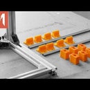
Step 3: Circuit Board


Here is how the circuit board will be wired. All the ground pins will be connected together. The pencil line denotes the ground line. The outputs will be connected to the raspberry pi using relimate cables.
A soldered PCB looks like the image shown above. At the back the connections are done using enameled copper wire to keep up with space. And for the ground wire I have just soldered it directly using silver wire.
Step 4: Configuring Retropie


I am using RaspberryPi3 but you can use anything you want. Attaching Joystick with a little bit of common sense will be the same on all boards. What would change however will be installing Retropie. Because based on your board they have different download options.
Installation:
So I downloaded the image and burned it on my SD card using Apple Baker. Then I inserted the SD card, HDMI cable, Keyboard and power cable. When I switched on the power the first boot up started. It will take you through the process of configuring the keys. Just follow the process by pressing each key as it says. I used the arrow keys on the keyboard for directions. The only key you must remember is Start, Select, A and B. Because these will be keys that you will use to navigate through the screen.
Once that is done enter the RetroPie using the A key. Scroll down to Wifi and connect to the wifi network. Once that is done press the Menu icon and exit the emulator. Now you must see your IP Address.
Setting Static IP
We have to set this as a static IP address. Static IP helps to connect to the raspberrypi from another machine using SSH everytime.
We need netmask and gateway addresses to create static IP. We get that by typing 'ifconfig'. The mask id is your netmaks id.
Then typing 'sudo route -n' shows the gateway id. Now that we have both these information we can create static IP. Enter the following to command to nano edit the interfaces.
'sudo nano /etc/network/interfaces'
Rewrite the page as follows:
auto lo
iface lo inet loopback
iface eth0 inet dhcp
allow-hotplug wlan0
auto wlan0
iface wlan0 inet static
wpa-ssid “YOUR_WIFI_CONNECTION”
wpa-psk “YOUR_PASSWORD”
address 192.168.0.125
netmask 255.255.255.0
gateway 192.168.0.1
The wpa-ssid is ur wifi name and wpa-psk is its passowrd. I want my static ip to 192.168.0.125 so I add that and then followed by other information. Press Ctrl+x to save the interfaces file and exit the nano editor.
Now I need to reboot using 'sudo reboot'.
Then if I exit the emulator we should see the new IP address that we gave.
Step 5: Using GPIO Pins:


Time to make the connections to the raspberry pi. Here is the pinout diagram of the GPIO Pins. If yours is a different version then search its relevant pinout diagram.
The ones marked in GREEN are the GPIO pins we can use. We will not use the SPI pins as we may need it if we are going to connect a TFT monitor. If we take out our PCB board we will need twelve GPIO pins. Four for the joystick and the rest for the tactile switches.
I have marked in the print out sheet which GPIO pins belong to which key. This will serve as a reference when I will solder the wires. Using some female headers I start counting from top and made the connections. We will be using this ground pin as our reference pin.
After soldering this is how it looks. All the circles marked in black are ground pins. But we will use the one in the last. The way this works is the ground pin is connected to one end of all the switches. When we press a switch we are basically grounding the pin hence sending an input to the retropie. Now lets configure the Retropie to accept these switches.
Step 6: Adafruit Library
Now back to the PC. But this time I will SSH using my Mac’s terminal. If you are on windows then you can use a free software called Putty. Typing ls shows the directory contents.
ssh pi@192.168.0.125
The default password is 'raspberry'.
We need the adafruit library and we can download it from the Github. I download the zip and saved it to the desktop. Then I exit the ssh using 'exit' command.
Using 'cd desktop' and then 'ls' command I check if the download is there. Then we can copy the adafruit library to pi using the scp command. Remember to put a colon at the end.
scp Adafruit-Retrogame-master.zip pi@192.168.0.125:
After typing the pi password which is raspberry in lowercase it transfers the files. Now I can ssh again and type ls to confirm if the file has been transferred. Yes I see the master.zip. I can unzip it now and typing ls shows the unzipped folder.
unzip Adafruit-Retrogame-master.zip
Using the rm command I will now delete the zip file to avoid confusion.
rm -rf Adafruit-Retrogame-master.zip
Then using the mv command I rename the unzipped folder to just Adafruit-Retrogame.
mv Adafruit-Retrogame-master Adafruit-Retrogame
Now I can cd inside the Adafruit directory and nano edit the retrograme.cfg file.
cd Adafruit-Retrogame
sudo nano retrogame.cfg
Here is where all the keystroke are mapped. Left represents the key mapped to the keyboard and the number is its respective GPIO pin that is mapped. The text after # is a comment just explaining what the key does.
So now keeping the GPIO pin out diagram as reference I input the correct GPIO pins. These pin numbers are the ones that I soldered the female headers to earlier. In the reference image the joystick UP key is mapped to GPIO4 which means I have to enter 04 into the config file, not 07. 07 is just the sequence number.
Pressing Ctrl+x saves and exits the file. Using the CP command I will copy the file to the boot directory. Because every time we start retropie this where it will look for the GPIO mapping info.
sudo cp retrogame.cfg /boot
Now I edit the local file so I can enter the absolute url of the Adafruit library which I copied earlier into pi directory.
sudo nano /etc/rc.local
Before the exit 0 line I paste this command. Again save and exit.
/home/pi/Adafruit-Retrogame/retrogame &
Now I need to add rules so that most of the games follow the limited keys that I have mapped.
sudo nano /etc/udev/rules.d/10-retrogame.rules
After pasting this command I can save and close.
SUBSYSTEM=="input", ATTRS{name}=="retrogame", ENV{ID_INPUT_KEYBOARD}="1"
Finally I need to run the retrogame command.
make retrogame
The make retrogame shows that all is good.
Again Reboot to make sure all is working fine.
sudo reboot
When it restarts now I can use my joystick to navigate.
After this you can disconnect your keyboard and start playing.
Step 7: Conclusion
And that’s how you can use the GPIO pins to input the controls to Raspberry Pi. My next effort will be to see how we can input two players controls just using GPIO pins. But if anyone of you know about how this can be done please put them in the comments below. I am trying to build an arcade machine and this will help.
If you repeat this project then tag me on social media as #mediamilan. I would love to check it out. And follow me on instagram @mrjcrp to see what I working on right now.
Until next time. Happy Learning.


