

Introduction: The Solar Design T-square and a Method for Designing Reflectors for Unattended Solar Cooking


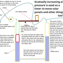


The first picture shows the design process and I have a pdf of that pic in the next step. (Much easier to see the details on the pdf)
Design an exotic reflector for unattended solar cooking. Your design might get used worldwide.
http://solarcooking.wikia.com/wiki/Solar_design_T-Square is the main page
I put in a new step 5 today (November 17th) with pictures to better explain it.
http://solardesign.ning.com/photo/albums/solar-design-tsquare (feb 9th) has pictures of models I made recently for 2 hour and one hour reflectors.
People say "why do it?" and "it cannot be done". Now companys in the western world are using carbon offsets to pay for the manafacture of parabolic solar cookers in India. They are even paying people to use them to cook their meals!
(In this way Solar energy is substituting for firewood and lets the forests regrow!)
But problems with light getting flashed in peoples eyes and having to constantly move the reflectors are being reported. These are BIG problems.
A dish for unattended cooking would alleviate the problems substantially.
It CAN be done! Check 5 minutes into this video for a (Probably patented) (and too complicated) design! http://www.youtube.com/watch?v=TSMzKg6fwJ8 and pause it at 5min 56 seconds in for the shape.
It is the tube horns that I am interested in. I believe 2 horns, lined up with the path of the sun is likely to be pretty efficient.
Here is another link with a picture to help get the idea
http://en.wikipedia.org/wiki/Holmdel_Horn_Antenna When you look at that picture, do you think of solar box cookers "with ears"!?
Please note that I use image notes extensively to explain
The method I choose is similar to "claymation" in that it will produce the grand design by a series of little steps. In this case, 2 laser levels are used to simulate the suns rays. If your design is to be unattended for 2 hours, then the laser levels shine at angles 30 degrees different to each other.
Step 1: The Design Process on One Page
I made one of these things in February but I did not do a good job as it was my first attempt and I scaled up from a model. If you do it, probably you would be better advised to make it full sized in one go. Anyway here is the picture of the design process. I also include the picture here as a pdf because that is much easier to read.
Attachments

Step 2: Compromise

I hate throw away disposable stuff. But the object is to make something anyone can make. And as small as possible. The laser pointers are powered by disposable batterys, you have to jerry rig them to stay on BUT they are cheap and very light.
It makes for light and easy to move apparatus.
Step 3: The Reflective Dish Problem

A year ago I made a compound parabolic dish that I thought would be a great improvement over parabolic dishes. It would have a much longer time when the cooking pot was being hit by the rays of the sun than a normal parabolic dish. I was correct for the area in line with the path of the sun and the target but areas outside that line did not perform so good.
This is a back to the drawing board experience!
Step 4: Concepts


The sun moves very close to 15 degrees per hour across the sky. So if you want a 2 hour reflector, you have a 30 degree difference between the suns angle first and the suns angle at the end of its time shining on the reflector. The idea is to have the 2 lazer beams shining and meeting at a point. Your solar reflector is working if when you bring this point onto the reflector, both beams hit the target.
If only one hits the target, then you have to adjust the angle of the strip of reflector until it hits.
Preferable it should hit with just one bounce. However it may be worthwhile to have it bouncing a few times if it increases the reflector size sufficiently.
Step 5: How to Set Up the Lasers and Model


Here we have a big grey area. Depending on your skills and equipment, you can either set up the lasers above the model and just have them going up and down like a microscope would. (and mostly move the model as you do your adjusting) or you can leave the model stationary and have the lasers doing all of the movement. You could even have the lasers attached to the edge of a sliding shelf. It slides out so that the lasers can be above any point on your model. The lasers must be able to move along the edge in this setup. Also, the lasers must be able to slide apart a little so that the intersection can move up and down and you can "focus the dot" on your strips of reflective material.
I include one drawing of how it can be done with the "sliding model" and I will add a diagram of the "edge of sliding shelf" concept later. (Just 2 different ways to achieve the same result).
I do not know which will be best in the long term.
Step 6: My System and My Model


Well, here is what I got done today, November 17th I got switches for the laser pointers (clothes pegs!) and I made the Tsquare, and angled the lasers properly.
I also show something of the start of a model. Here I ran into problems because I do not have suitable strips of material for the backing of the reflective mylar. But not bad progress, i think.
See the photo's for the progress. I use image notes to explain more of the detail.
Brian
Step 7: You Only Need to Make a Quarter of the Design!


Because of basic symetry you only need to use this method to make a quarter of the reflector.
When the shape becomes clear it can just be transfered to the other 3 quarters.
This means that the design process is not as tough as it first seems!
Step 8: Strips or Slices?


For first making the design, perhaps equal strips of reflective material are best. I concidered using a square or circular piece of material and then making cuts radiating from the center.
This might work but it is probably harder to handle cuts that get wider the further they are from the inside.
Strips all the same width are probably easier to handle because you can make standard pieces and wedges to keep them in place after you adjust them.
Also, in the design phase, gaps may be fine. It may even be helpful as you try to find the complete shape.
Step 9: Starting Your Model

My model has not been turning out like I expected. (But that is ok)
From making the model, I though of a few things.
1. It is sometimes hard to see where the reflection bounces on the ball. Sometimes it is on top, bottom or side.
2. No ball is needed if you just make a round hole at the back of the reflector. That might be the easiest way because then all you have to do is have a white sheet of paper over the hole and you can always see the laser dots on the paper if it is properly adjusted!
First of all I got a red ball to represent the cooking pot. This can be suspended a few inches above the table or screwed into the table at that height.
Below the cooking pot, you must have your strips of reflective material laid out. The ideal material might be a thin plastic with reflective material stuck on it.
I might drill holes in the bottom of all the strips and attach them all to a center using a pin or small nail.
I still have not figured out how best to keep the strips in position as I and after I adjust them to the laser points.
I show a procedeure to adjust the strips in the image notes.
If you are willing to have 2 or more bounces of light and (if you want to produce a more exotic beautiful shape), Then I suggest you start at strip 10 and work backwards. As your reflections start to go out of range and start missing the target, start using strips 1,2, etc to redirect them!
In this way, you both enlarge the reflector shape and get an exotic and perhaps beautiful shape!
Happy modeling.
Brian
Step 10: Refining the Shape
You can take the designing as far as you want. You might end up with the strip design or you might want the complete shape to be stamped out of one piece of material. It is up to you how far you want to go. I do not think any design that you make with this method can be patented. I think that long term that will be an advantage.
Step 11: Tradeoff Time. Sine Rules and Bounces.
Tradeoffs are important. For a 2 hour solar cooker, you would line it up with the path of the sun and put it 1 hour (about 15 degrees) ahead of the sun. For the next hour the sun moves from 15 degrees off target to directly above and then spends another hour going off target again. The area of sunlight that reflects to the target is related to the sine of the angle. Directly overhead, the sine is 1, one hundred percent of full power. 15degrees off is 75 degrees and the sine of 75 is about .9659 so (assuming one bounce to the target) your dish at its worst will be 96.6 of the power of the same size parabolic dish!
And its average power over those 2 hours will be 98% or better WITHOUT HAVING TO BE THERE TO ADJUST THE DISH. But of course, you might have to do 2 bounces in some places.
With a 3 hour dish, the sine goes from .924 to 1 and back to .924 so a lot more loss. Perhaps you only get 95% over the 3 hours. And with 4 hour dishes, you go from 86.6% to 1 and back to 86.6%
So you get tradeoffs depending on how unattended you want your dish to be.
At some points your design may have 2 or even 3 bounces of light before you get to the target.
You can assume 10% loss at each bounce. 1 bounce is the same as a normal parabolic dish so first bounce does not count. 2 bounces is 90% and 3 is 0.9 X 0.9 = 0.81 4 is 0.9 X 0.9 X 0.9 = 0.729
so we get tradeoffs whereever we go!
Hopefully people will use this idea to design dishes with the right amount of tradeoffs for their own situations.


