

Introduction: Mini Space 1999 Eagle Popsicle Stick Model


Hello everyone! Have time? How about a very intricate project from a Gerry Anderson concept - a mini popsicle stick Space 1999 Eagle spacecraft from Moonbase Alpha!
The Eagle multi-purpose transporter was the primary spacecraft from the 70's Sci-fi series Space 1999. With a unique modular design, the spacecraft was designed to carry various types of specialized pods. A number of pods, particularly the standard passenger pod, winch and laboratory pods were modeled in this instructable.
The mini popsicle stick version of the Eagle was, to say the least, very challenging to build. The support frame connecting the aft and service modules took a lot of time to fabricate because of its intricate, lattice-design feature. Just waiting for each single piece to dry in place took a long time. Overall, I was very satisfied with how final the spacecraft came out after completing it 'one-stick at a time'.
This project is dedicated to my Virginia-based sister Maria who supplies the special tools and equipment used in all my builds.
Step 1: Materials and Tools


I've got a chance to use the Dremel Workstation for this project. The moto tool mounted on the workstation freed both of my hands to twirl the small delicate parts to get the desired shape. This was especially useful for shaping the main support frames.
Other tools used were:
- Dremel 3000 and MiniMite with the following attachments
- 1/2" coarse/fine drum sander
- 1/4" fine drum sander
- coarse/fine disk sander
- regular and reinforced cutting wheel
- #85422 grinding stone
- #124, #125 & #191 high speed cutters
- Various clamps
- Olfa Cutter
- Stanley cutter
- Fine tweezer
- Mechanical pencil
- Ruler
- Cutting Mat
- Elmers white glue
Step 2: Schematics and Images


As usual, the web was aplenty with resource materials from the 70's series. Keywords used for both Bing and Google images were "space 1999 eagle".
The schematics I used in this instructables were from the following URLs:
http://republibot.com/sites/default/files/images/eagle_1.jpg
http://catacombs.space1999.net/main/merc/blueprint/ivmblueagle1.jpg
http://catacombs.space1999.net/cybermuseum/Fans/Roberto/EXT.JPG
Images used for some of the details were from the following URLs:
http://www.fxmodels.com/Space1999/Eagle-2.jpg
http://www.fxmodels.com/Space1999/Eagle-3.jpg
http://www.fxmodels.com/Space1999/Eagle-1.jpg
(thanks Ed!)
Again, my sincere thanks to the providers of images and schematics used in this instructable. This wouldn't be possible without them!!
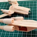
Step 3: The Command Module and Main Engines


I began the project with the fabrication of the Command Module and main engines. This was a departure from my previous projects where I would normally begin with the single, biggest piece of the spacecraft.
Eight (8) 'heart' shaped pieces were cut from tongue-depressor sized sticks. Six (6) of the 'heart' shaped pieces were further cut for the top and bottom parts of the command module. The remaining two (2) pieces formed the center base of the command module.
After the eight pieces were sandwiched together, a course/fine drum sander attachment mounted on a Dremel 3000 was used to carve the command module to the shape illustrated in the schematics and images. The completed command module was finished with a fine disk sander attachment on a Dremel MiniMite.
For the four (4) main engines of the Eagle, regular sized coffee stirrers were sandwiched together. The sandwiched, single piece was then carved into a dowel-shaped piece using a coarse/fine drum sander attachment mounted on a Dremel 3000. To carve the cone-shaped thrust nozzle, a fine drum sander attachment was set at an angle and the wooden dowel carefully twirled. A Dremel Workstation mounting the moto tool came in handy for this, freeing both of my hands to twirl the wooden dowel.
For the engine exhaust, a pilot home was made using a #125 high speed cutter attachment. The hole was made bigger, first with a #124 high speed cutter bit and then with a #191 high speed cutter attachment mounted on a Dremel MiniMite.
I cut the entire assembly allowing for the carving of the egg-shaped plasma accelerator in front of the thrust nozzle. The egg-shape was finished with a fine drum sander attachment on a Dremel MiniMite.
The four main engines (plasma accelerator + thrust nozzle) were interconnected together into a single assembly with four (4) pieces of tiny wooden tubes. The tubes were made from thin toothpicks. Two (2) tubes connected the first pair of engines. The last pair was glued between the first pair with another set of two (2) tubes to complete the engine assembly.
Step 4: Supporting Frame and Service/Engineering Modules


To make the main struts of the supporting frame, I drew a series of markings on a regular sized popsicle stick based on the top-view schematics from Step 2. The marks provided a guide in grinding the thinner struts of the support frame. I used a #85422 grinding stone for the wider spaces and a cutting wheel for scribing the much smaller spaces. I then each of the four (4) struts with an Olfa cutter. Each strut was further thinned and rounded using a combination of grinding stones and fine disc sander attachment on a Dremel Minimite.
For the cross braces that connects the top pair of struts, thinned toothpicks were used. Each cross brace was glued to the strut at the thicker 'junction' using the top view schematics as reference. The completed top frame must now resemble a tiny 'ladder'.
The bottom struts were a segment longer than the top set. Two (2) longer cross braces were glued at both ends of the bottom struts. Thinned toothpicks were used to join the top 'ladder' with the bottom strut.
Now comes the really tedious part - the vertical and diagonal braces between the two struts. Thinned toothpicks were custom cut and glued to the space between the top and bottom struts, one piece at a time. I estimate that it took me approximately more than two (2) days to complete the support frame.
The front service and rear engineering modules took a lot less effort to make. Ten (10) layers of regular-sized popsicle sticks cut, glued and sanded into shape were needed for each module. The completed support frame connected the two modules together.
Thinned toothpicks were again used for the horizontal, vertical and diagonal braces around the front and rear engineering modules. Approximately another two (2) days were needed to completely envelope the service/engineering modules one small piece of toothpick at a time.
To complete this major sub-assembly, I needed two thick wooden coffee stirrers to make the vertical action turbojets. Four (4) were glued at the bottom of the completed supporting frame and service/engineering modules. Another dozen vertical action turbojets were made for the various specialized pods described in the succeeding steps of this instructable.
Step 5: Eagle Transport Pod


For this project, I decided to include three specialized "pods":
a) Transport Pod (with landing pads in retracted position)
b) Laboratory Pod (with landing pads in deployed position)
c) Winch Pod (with landing pads in deployed position)
An image from Designinspiration (thank you guys!!) provided a good reference for the Eagle "Pods". URL for the image is http://cdn.iofferphoto.com/img/item/747/338/26/y8vn83LMeMgClZZ.jpg
Transport Pod
The standard transport pod is used to transport moonbase personnel and equipment. A similarly shaped pod, the rescue pod is recognizable by vertical red stripes and used to transport life-saving and rescue equipment.
The popsicle stick transport pod was made from twelve (12) layers of regular popsicle sticks cut to fit the space between the service and engineering modules.
The trapezoid shape of the pod was carved using a coarse/fine drum sander attachment and finished with a disk sander mounted on a Dremel moto tool. The notches on top of the transport pod (for the support frame) and the docking hatches (on both sides of the pod) were carved using a grinding stone and 1/4" drum sander attachment.
I laminated a single piece of tongue-depressor below the pod to increase the height as illustrated in the schematics. Guide marks were drawn for the vertical turbojets and landing pads of the transport pod. Four (4) vertical turbojets (from the previous step) were glued to the bottom of the transport pod. I initially tried to drill a hole at each vertical turbojet using a #125 attachment but decided to abandon this since the part had a tendancy to split in the middle. Hence, the model depicted has solid vertical turbojets.
A thin, wooden coffee stirrer and toothpick from my spares box were used for the landing pad pieces. Three shapes make up a landing pad assembly: a triangular base, a tiny tube for the shock absorber and rectangular 'pad'. The triangular base and tiny tube were glued adjacent to each other parallel to the vertical turbojets and allowed to dry. In the retracted position, the landing pad was glued at an angle from the apex of the triangular base.
Step 6: Laboratory Pod


Laboratory Pod
For the Laboratory pod, the image from the URL http://www.ize-stuff.com/picture/stuff/movie_stuff/sci-fi_stuff/Space%201999%20Laboratory%20Eagle%20Limited%20Edition%20Replica.jpg was used as reference.
The laboratory pod retains the same basic shape of the transport pod with an extended access hatch at both sides. The access hatch was made from eight (8) regular sized popsicle sticks cut to size using the image as reference. Another two (2) tongue-depressor sized sticks were used to laminate the base shape to account for the additional height of the access hatch. The final, trapezoidal shape of the extended access hatch was carved using a coarse/fine 1/2" drum sander attachment on a moto tool.
The extended access hatch assemblies were glued at both sides of the base transport pod. Marks were drawn at the bottom of the laboratory pod to guide the placement of the six (6) vertical turbojets and four (4) landing pads. The landing pads for both the laboratory pod and winch pod were wider than the pads for the transport pod. A single tubular toothpick for the shock absorber also differentiates the landing pad assemblies of the laboratory and winch pod with the landing pad of the transport pod.
Another distinct feature of the laboratory pod was the placement of four (4) reaction control thrusters on both sides of the extended access hatches. Similar thrusters were also a feature on the side of the landing gear assemblies of the Eagle transport.
Each thruster assembly was made from thin scraps of wooden coffee stirrers (for the base) and toothpick ends (for the thruster exhaust). The toothpick ends were tapered using a fine drum sander attachment on a MiniMite. The tapered ends were cut to get the cone-shape of each thruster exhaust.
The tiny square thruster base was glued first to the side of the access hatch. Each cone-shape thruster was glued with the tapered ends pointing to the thruster base. This process was repeated four times to produce the results in the instructable images.
To complete the laboratory pod, access doors made from spare wooden coffee stirrers were glued to the end of the access hatches.
Step 7: Winch Pod


Winch Pod
For the Winch Pod, the following images from the URLs below were used as reference:
http://www.space1999.org/images/gallery/jmurphy/jamesmurphy_eagle5.jpg
http://spaceart.de/produkte/mondbasis_alpha_1_freighter_pod_eagle_transporter_ga037-a.jpg
Unlike the solid, rectangular transport and laboratory pods, the winch pod is basically a flat, open platform with cylindrical winches.
The cylindrical winches were made from laminated, thick wooden coffee stirrers shaped and cut to size. The winch mount and details were from parts from the scrap "box".
The platform frame was made from similarly thin toothpicks cut and glued using the pattern in the images. A frame base anchors the skeletal frame to the winch platform. I originally planned to include the magnetic clamp in this model but thought that it would be useless to display it separately. A hole for the cable was drilled on the platform for this purpose.
The winch pod's landing pads were built similar to the laboratory pod's landing pads. The vertical turbojets were fabricated earlier in Step 4. The four (4) landing pads and four (4) vertical turbojets were glued directly beneath the platform at points similar to the landing pads and turbojets of the transport pod. To complete the winch pod, the winch itself was glued on the top of the platform.
Step 8: Outboard Fuel Tanks and Landing Gear Assembly


Each of the four (4) octagonal outboard fuel tanks were made from six (6) layers regular sized popsicle sticks cut and shaped based on the schematics. A #85422 grinding stone and fine drum sander attachment mounted on a Dremel Minimite were used to carve each octagonal fuel tank. The outboard fuel tanks mounted the Eagle's landing gear assembly.
The landing pads were shaped from tongue depressor-sized popsicle sticks using an Olfa cutter. A tiny rectangle for the suspension base was made from a spare, thin wooden coffee stirrer and glued on top of each landing pad. The main suspension was from thin toothpicks and glued on top of the suspension base. The completed landing pad and suspension assembly was installed beneath each outboard fuel tank.
The tiny, v-shaped landing stabilizer was made from two (2) thin toothpicks glued together. Each of these were mounted between the suspension base and main suspension. The four (4) struts of each landing gear assembly were also made from thin toothpicks.
The reaction control thrusters mounted on each of the octagonal were similarly made like the thrusters described in Step 6: Laboratory Pod. Hence, the materials and steps were the same as described in Step 6.
Step 9: Final Assembly


To prepare the fuselage assembly for the installation of the completed outboard fuel tanks and landing gear assemblies, scraps were glued between the lattice frames. The spacers provided a larger surface area to bond the outboard fuel tanks with the fuselage.
The only small parts needed to complete the Eagle were the round deuterium tanks and plumbings mounted between the engine exhausts. These were made from basically two parts, tiny toothpicks and a laminated wooden coffee stirrer.
I found it easier to make each deuterium tank from two (2) halves of tiny domes glued together than carving a whole circle from a laminated wooden coffee stirrer even with both hands free with the aid of the Dremel workstation. With this process, I needed to make eight (8) tiny domes for the four (4) tanks.
For the plumbings connecting the tank to the engine exhaust pipes and rear fuselage, two (2) steps were needed: (1) tiny toothpicks were glued at a right angle and cut to size with an Olfa cutter and (2) each completed plumbing set was glued to the front and back of each deuterium tank.
Before I could mount the tank and plumbing between each engine nozzle, I had to make a last minute adjustment by removing one vertical piping on one side of each tank. There was simply no room to mount the assembly in place with two (2) right-angled piping system in place.
After making the necessary adjustments, each set of deuterium tank and plumbing was glued between massive engine nozzles with the right-angled piping connecting to the engine piping system.
To complete the Eagle, I had to make a special jig composed of eleven (11) laminated tongue depressor-sized sticks to fit between the support frame. The jig props up the spacecraft while the glue between the outboard fuel tank assembly and spacer dries. I also had to use another jig to support the command module while the bond between the front fuselage and command module dries.
And there you have it, a multi-purpose spacecraft to support Moonbase Alpha!!!


