

Introduction: MiniMin - a Theremin Style Instrument From 6 Components


The aim of this project is to build a playable Theremin style instrument using the minimum number of components. The Theremin is an electronic instrument played by moving both hands in close proximity to the device. It requires no physical contact between the player and the instrument. A conventional Theremin uses electromagnetic fields to sense the distance of the players hands from two antennae. The MiniMin uses two low cost ultrasonic distance detectors controlled by an Arduino micro-controller.
Learning to play a traditional Theremin is notoriously difficult. For this reason, the MiniMin has a 'cheat' mode where the pitch will 'snap' to the closest musical note in a scale. Four musical scale options are provided :-
- Chromatic
- C Major
- C Minor
- C Minor pentatonic
Additional scales can be added simply by defining an array of frequency values. Traditional behaviour or 'snap to scale' mode can be selected when the Arduino sketch is compiled.
Supplies
The MiniMin comprises only six components: -
1 X Arduino microcontroller - I used an Uno but any compatible should work
2 X Ultrasonic range sensors - I used the ELEGOO HC-SR04
1 X 270 Ohm resister
1 X 100 nF capacitor
1 X Audio output socket (6.3mm or 3.5mm)
The circuit is simple enough for point-to-point hand wiring or you could use a breadboard or perfboard.
The MiniMin runs happily off USB power so no special power supply is required.
You will also need a PC with the Arduino IDE installed to load the software.
Step 1: How It Works
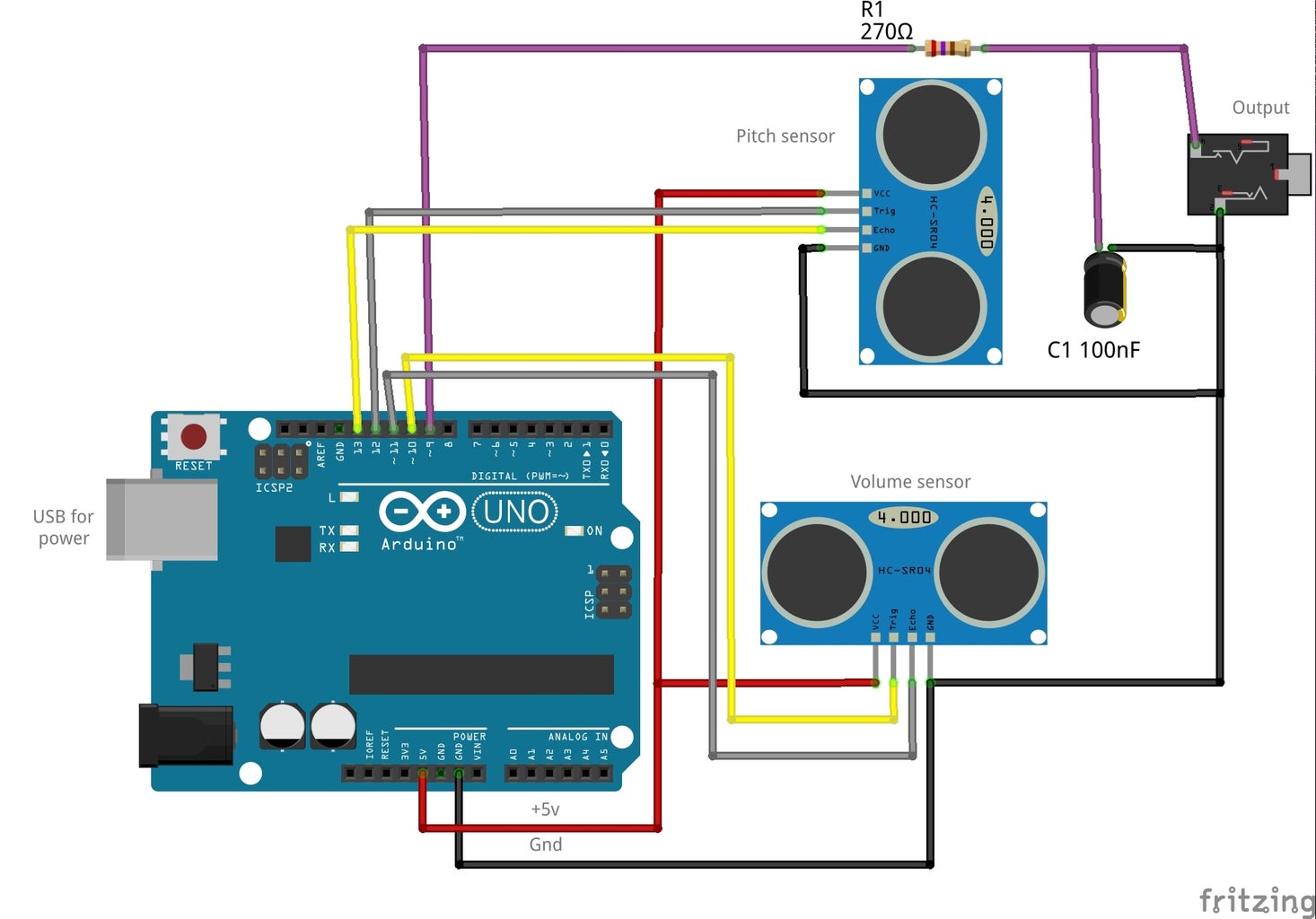
The circuit for the MiniMin is shown above.
The two Ultrasonic range detectors replace the antenna of the traditional Theremin. One controls the frequency (pitch) of the output and the other controls the amplitude (volume). Operation of the sensors is straightforward. The Arduino sends a digital pulse to the TRIG pin of the sensor causing it to emit a burst of high frequency audio. If an echo is detected the sensor toggles the ECHO pin which is monitored by the Arduino. By measuring the time delay between the outgoing pulse and returning echo we can calculate the distance. As sound takes 29 microseconds to travel one cm, and must travel out and back, we can divide the time to the echo by 5.8 to get the distance in mm (the project uses time/6 as an approximation).
The audio output is generated using Pulse Width Modulation (PWM) to reduce the component count. It requires only one capacitor and resistor connected between the PWM output (digital pin 9 on the Uno) and the output socket. The PWM output is a string of digital pulses. If the pulses are high enough frequency they will charge the capacitor and give a rising voltage on the output. If the pulses are of low frequency the capacitor will discharge and the output voltage falls. By varying the pulse frequency (or pulsewidth) a waveform can be generated. Although this kind of PWM audio is fairly low quality it is good enough for this application. The project uses the Mozzi audio library to generate a triangle wave which is sent to the output.
The MiniMin has a usable range of around three octaves which is comparable to a mid-range analogue Theremin. The sketch uses a tuning range of C4 to C6 (one octave below Middle C to two octaves above) which can be changed by editing the values of 'lowestFreq' and 'highestFreq'. Similarly, the operating distance of the sensors can be tweaked by changing the 'low' and 'high' threshold values.
The two sensors of the Minimin are placed at 90 degrees to each other, similar to the antennae on a regular Theremin. The distances measured are mapped to frequency and volume variables which are applied to the Mozzi oscillator.
Line 22 of the sketch determines the operating mode of the MinMin. If set to 'false' it will operate as a traditional theremin with a constantly variable frequency response. If set to 'true' the MiniMin will choose the closest note in the selected scale.
const boolean stepMode = false;
The desired scale is selected by 'uncommenting' the corresponding array of frequency values (lines 24 - 42 of the sketch).
The complete sketch can be found on my GitHub page.
Step 2: Demo and Future Plans
The video above gives a brief demo of the MinMin (external delay and reverb effects have been added). The current version is very much a breadboard prototype. The next step is to choose a suitable enclosure and hard wire the components. I like the idea of using a short length of drainpipe with a 90 degree elbow to keep the sensors at a right angle. Swapping the Arduino Uno for the smaller Nano would allow a more compact case to be used.
The aim of this project was to use as few components as possible. However, the addition of a some extra hardware could greatly increase the functionality. Some simple switches would allow different waveforms, mode, scales and octaves to be selected. Next job - the MiniMinMax!

Participated in the
Instrument Contest

![Tim's Mechanical Spider Leg [LU9685-20CU]](https://content.instructables.com/FFB/5R4I/LVKZ6G6R/FFB5R4ILVKZ6G6R.png?auto=webp&crop=1.2%3A1&frame=1&width=306)


