

Introduction: Neopixel Clock


Do you want to build a nice LED clock? If you say yes please keep reading and don't miss anything in this Instructable, we are going to build the clock of your dreams. (okay maybe not, but you have to admit that at least it sounds cool)
First of all, this clock uses RGB leds to display the hour, minutes and seconds. The minutes and seconds are represented in multiples of five. The hour is displayed by red colour, the minutes by green and the seconds in blue. When they are in the same number the color mixes up in a nice way.
As an extra I made an infrared remote control. It allows to change the time, the logo colour and the numbers colour. You should watch the video in order to understand me.
This clock is powered by USB and have been made with laser cut acrylic.
Step 1: Materials


To build this clock you would need:
- 1 x Arduino pro mini + serial converter (to load the program, you can use your Arduino Uno for this)
- 1 x RTC module DS1307
- 19 x Neopixel (WS2812B) with breakout board for wire soldering.
- 1 x TSOP1838 (only if you build the remote, or you can use any IR control. Just modify the code)
- 1 x SMD mini USB connector.
- 1 x 330 ohm resistor.
- 4 x M3 screws, 20mm long.
- 2 x M3 screws, 6mm long.
- A lot of flat wire.
If you want to build the infrared remote you will need:
- 4 x SMD push buttons.
- 1 x PIC 12F1822.
- 1 x CR2032 SMS battery holder.
- 1 x Side mount SMD IR led.
- 2 x M3 screws, 12mm long.
And of course the laser cut parts, that you can download from here: https://github.com/DAFRELECTRONICS/Neopixel-Clock....
Also you can find the PCB's used in this link.
Step 2: Assembling the Acrylic Parts for the Clock


After you laser cut the parts using the files in GitHub, the first step is to remove the protective film of the acrylic.
Then insert the four 20mm M3 screws in the clear acrylic holes, then put the part with the numbers and after that put the circle that have 2 holes in the bottom. After that put the two pieces that have the opening in the bottom. It should align perfectly. Don't put the cover yet.
Now insert the white acrylic ovals in the slots, attach them with hot glue from the inside of the clock. Now put the white ring and the center in place. I used double side tape to hold it in place.
That's all, it was easy right? But we have not finished yet.
Step 3: Building the Circuit


The only board that you will need to make is the USB breakout, we recommended have this one before getting started with this step.
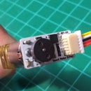
Get ready for a lot of soldering. First we are going to solder our strip of neopixels. Solder the 19 Boards using flat wire in chain, 5v with 5v, GND with GND and SO with SI. Make sure the wire between each board is enough to put the neopixels on top of the white acrylics as shown in the picture. The first neopixel leave only with the wires soldered but don't solder it yet to the arduino.
Now the hard part begins, solder the 5v and GND of neopixel chain to the 5v and GND of Arduino. After that also solder the 5v and GND from the USB conector and TSOP1838(optional) to the same 5v and GND of the arduino. Do the same with the RTC module.
The neopixel chan serial In (SI) is soldered to arduino pin 6 with the 330 ohm resistor in series. The SDA and SCL to A4 and A5 in the Arduino. And the TSOP1838 output pin is soldered to arduino pin 10.
Now use hot glue to attach all the electronics in place, the USB breakout is attached using the 6mm screws. And the TSOP1838 is under this board having his body out of the clock. Just in front of the USB conector.
Note that first are the neopixel that lights the center, then 6 for the numbers and finally 12 neopixel for the numbers starting from the number eleven to the number 12 of the clock (11,10,9,8....3,2,1,12)
Step 4: Load the Code


Use your Arduino UNO or a serial adapter to burn out the program in the pro mini. The hour is set automatically from your computer at compilation time in the Arduino IDE. Your clock must be operative and at the right time now.
Step 5: Final Assembly


Put the cover and use the screws to tighten it in place. Put the USB cable in place and power it up. Now we have a nice looking Neopixel clock.
This is a work in progress, so the control remote steps will be pending. Don't worry, If you are brave enough I have included the board layout and PIC microcontroller program in the git download. So please check it out while I finish this Instructable.
Thank you for reading, I hope you enjoy it.

Participated in the
Time Contest

Participated in the
Make It Glow! Contest

Participated in the
Tech Contest

![Tim's Mechanical Spider Leg [LU9685-20CU]](https://content.instructables.com/FFB/5R4I/LVKZ6G6R/FFB5R4ILVKZ6G6R.png?auto=webp&crop=1.2%3A1&frame=1&width=306)


