

Introduction: Object Tracking Camera Slider With Rotational Axis. 3D Printed & Built on the RoboClaw DC Motor Controller & Arduino


This project has been one of my favorite projects since I got to combine my interest of video-making with DIY. I’ve always looked at and wanted to emulate those cinematic shots in movies where a camera moves across a screen while panning to track the object. This adds a very interesting depth effect to an otherwise 2d video. Wanting to replicate this without spending thousands of dollars on Hollywood gear, I decided to build such a camera slider myself.
The whole project is built on parts you can 3D print, and the code runs on the popular Arduino board. All the project files such as the CAD files & code are available for download down below.
CAD/ 3D print files available here
Arduino Code file available here
The project revolves around the 2 geared brushed DC motors and the Basic Micro Roboclaw Motor controller. This motor controller can transform brushed DC motors into a superior type of servo with incredible positional accuracy, tons of torque, and a full 360 degrees of rotation. More on this later.
Before we continue, do watch the video tutorial linked here first. That tutorial will give you an overview of how to build this project and this Instructables guide will go more in depth in how I built this project.
Materials-
- 2x 1 meter long m10 threaded rods used to connect all the parts
- 8x M10 nuts to mount the parts to the threaded rods
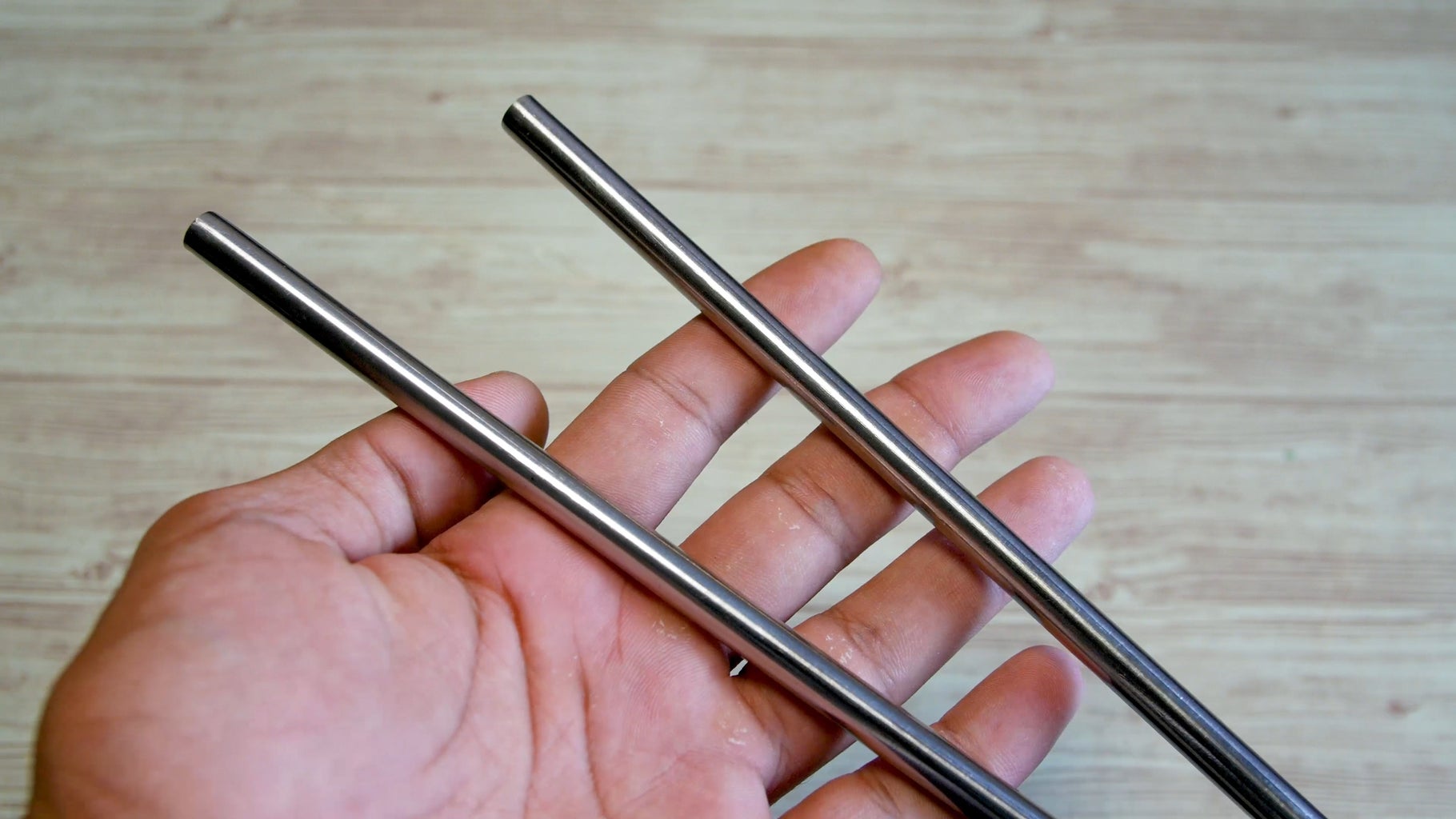
- 2x 95 cm long 8mm smooth steel rods for the slider to slide on
- 4x lm8uu bearings for the slider to smoothly slide on the steel rods
- 4x 10mm long m3 nuts for mounting the motor
- 2 x skateboard bearings (22mm outer diameter, 8mm inner diameter) for the rotational axis
- 1x 15mm bearing for the idler side
- 1x 4cm long m4 bolt with m4 lock nut for mounting the idler bearing to the idler 3d printed part.
- 20 teeth gear with 4mm inner diameter for the slider motor. The exact pulley isn't very important since your DC motor should be geared for enough torque. Just make sure it is the same pitch as your belt
- 2 meter long GT2 Belt. Again you can use any belt as long as it matches the pitch of your pulley's teeth.
Electronics-
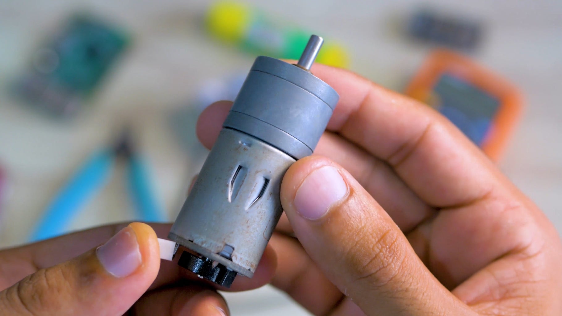
- 2 * Geared DC motors with encoders (one controls the lateral movement, while the other controls the rotational axis). Here is the one I used. More on this in the Electronics part of the guide
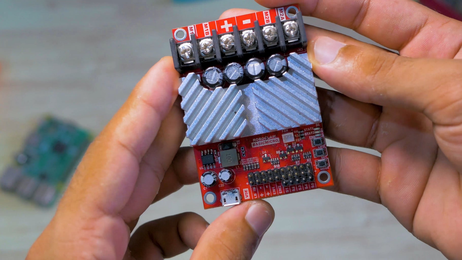
- RoboClaw DC motor controller. (I used the dual 15Amp controller since it allowed me to control both motors with one controller)
- Any Arduino. I used the Arduino UNO
- Battery/ Power source. ( I used a 7.4V 2 cell LiPo battery)
- Screen (For displaying the menu. Any U8G compatible screen will work, I used this 1.3 inch OLED screen)
- Rotatry encoder (For navigating and configuring options in the menu)
- Physical push button (For triggering the slider’s movement)
Step 1: Hardware Design + Build + 3D Printing
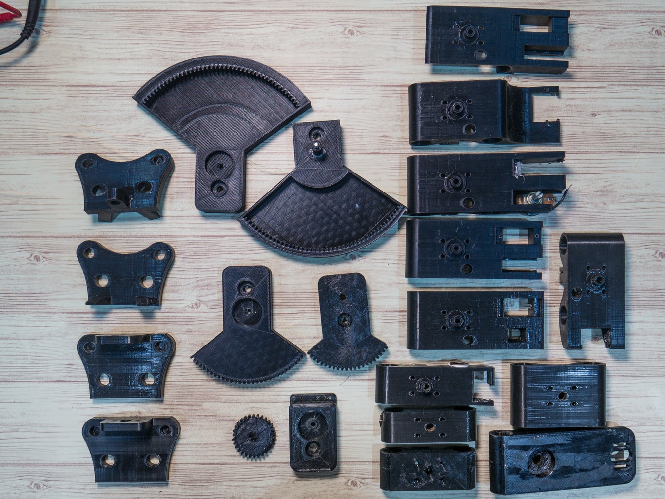

As the first step of building the slider, we are going to start with the physical parts. All the parts were designed to be 3D printed and the STEP and STL files can be downloaded here
As you can see from the pictures above, there are a lot of individual parts. I will briefly cover their purpose here
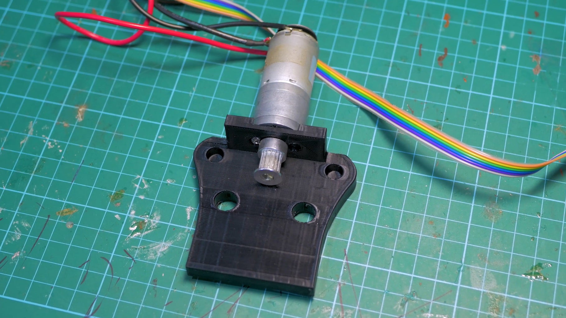
Motor mount- This part holds the motor that is responsible for moving the camera laterally. This part also acts like the stand for the project. The part is attached to the electronics enclosure via the 10 mm threaded rods and m10 nuts.
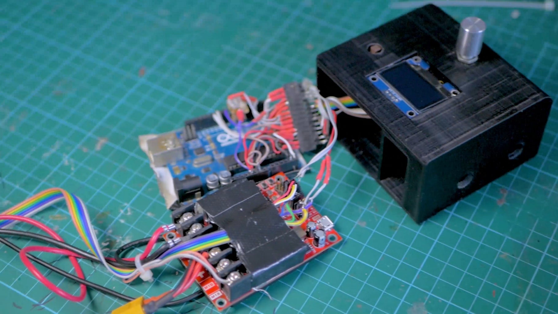
Electronics enclosure- This part houses all the electronics that control the camera slider. The Arduino & the Roboclaw motor controller slide into the main, big, compartment. Next to that is a smaller compartment for your batteries. I sized this compartment for this battery but you can modify my files for your battery. The 2 M10 nuts also go into the recessed hole here to attach your electronics enclosure to the motor mount via the M10 threaded rods. At the top of the electronics holder, there is a recessed slot for your screen and holes for your rotary encoder and start button.
Idler- Opposite the motor mount+electronics, on the other side of the slider is the Idler side. The idler part uses a ball bearing to let the belt spin freely. This part is also secured to the camera slider via the M10 threaded rods using the M10 nuts to clamp both sides of the part.
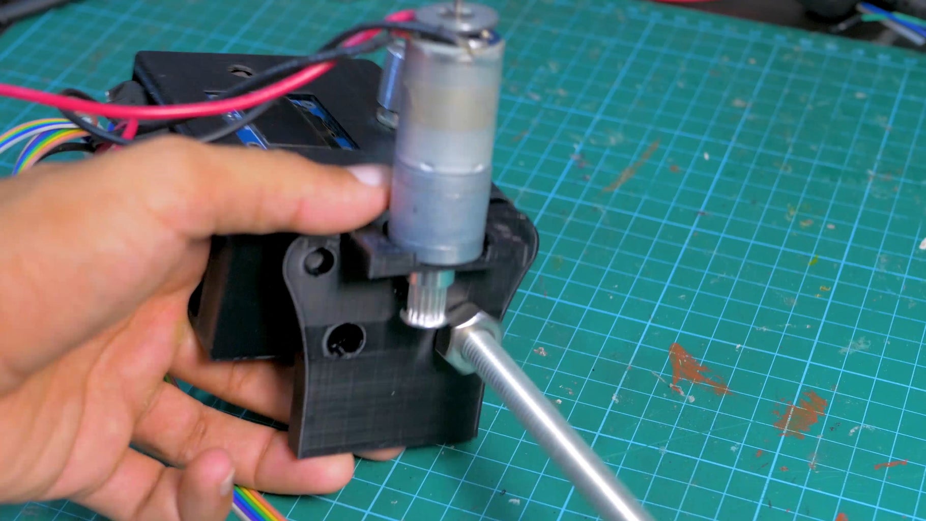
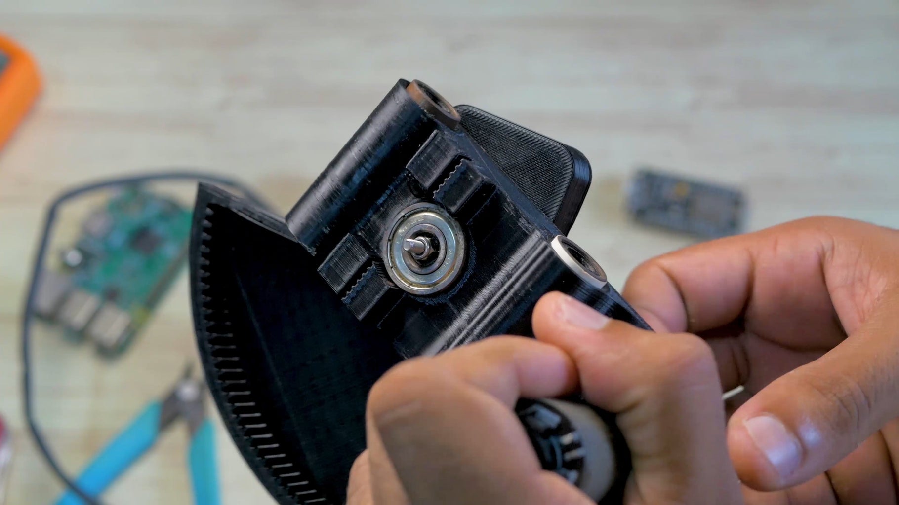
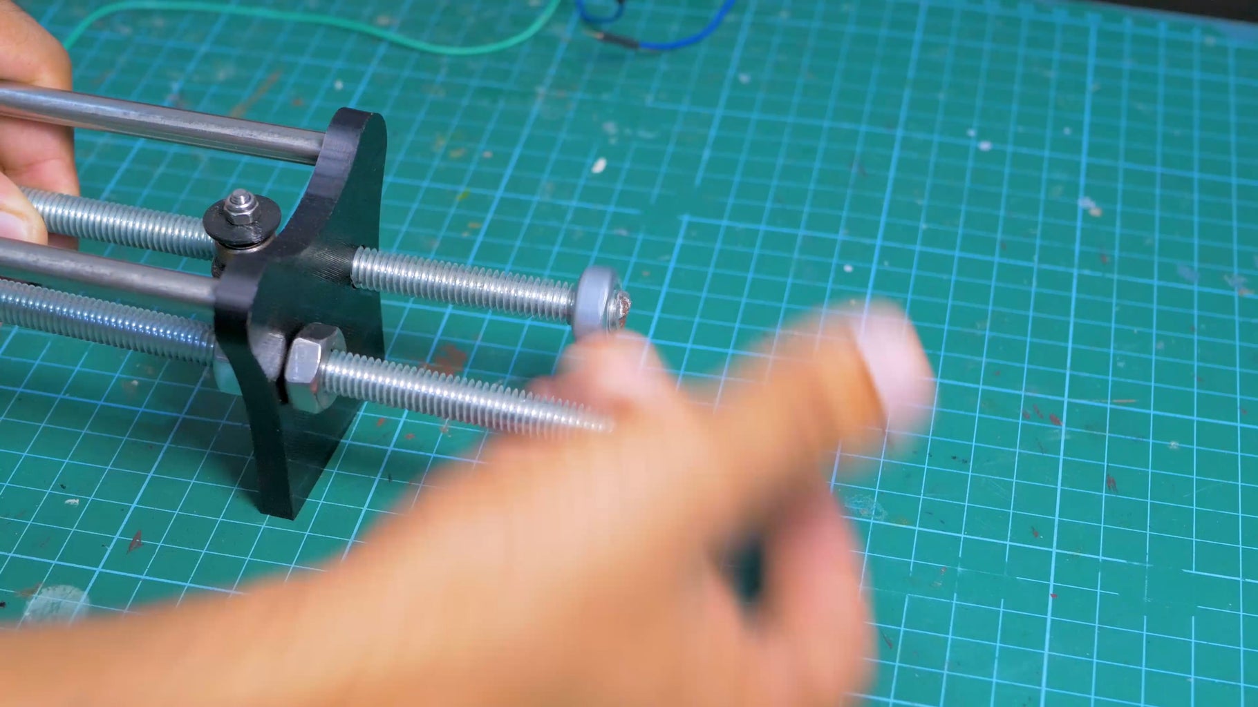
Slider Base- This part is the part that actually moves side to side when the slider’s main motor spins. This part is attached to the 8mm smooth rods via 2 lm8uu bearings per side. I used 2 bearings to stabilize the platform and prevent vibration. This part also has Gt2 belt teeth printed to the bottom of it so you can easily attach your belt from the motor mount to this part. This part uses 2 standard skateboard bearings on both sides of the part. These bearings attaches the camera mount part to this slider base and allows the camera mount to rotate freely with minimal friction. Lastly there is also space to attach the rotational motor to this part. The motor mount is designed so you can slide your motor before tightening to ensure optimal connectivity between your motor’s gears and the camera mount’s gears.
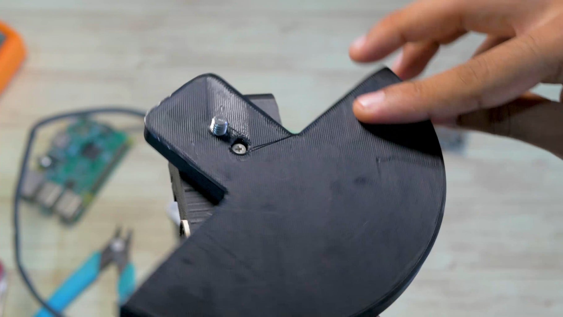
Camera mount- This part is quite unique as well. It has a hole for the quarter inch screw that can be used to attach the part to any camera. This part also has a cylindrical extrusion that fits inside the slider base through the 2 ball bearings. This helps prevent friction. Lastly the part has internal ring gearing that interfaces with the rotational motor in the slider base and helps rotate the camera holder.
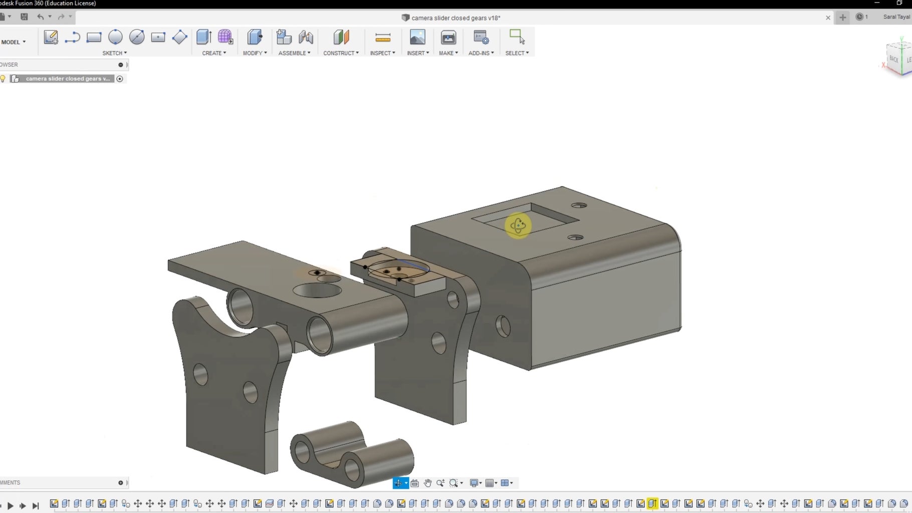
How I designed the gears:
Building this project, I made roughly 30 prototypes of which 15-20 of them were gears. I wanted to ensure maximum smoothness + accuracy so I had to use a high gearing ratio (Big motor movement = small camera movement). What made it really easy to try out different gears without having to re-CAD everything was using Fusion 360’s McMaster integration. By clicking on the add part tab in Fusion 360, I could open up the whole catalog of McMaster parts and simply select the gears I needed. Doing so allowed me to import CAD versions of those gears into my project and I could simply add them to my existing parts without having to CAD them myself.
Step 2: Electronics
Next let's move on to the electronics. The electronics is where this project has a lot of flexibility.
Let’s start with the core of this project- the 2 brushed DC motors.
I chose brushed DC motors for a few reasons.
- Brushed motors are much more simple to wire and operate compared to stepper motors
- Brushed DC motors are much lighter than DC motors which is especially important for the rotational axis motor since that motor is physically moving laterally with the camera and making that as light as possible is important for preventing excessive strain on the primary camera slider motor.
I chose this particular DC motor. This motor gave me an extremely high amount of torque which was necessary for moving such a heavy camera load. Furthermore, the high gearing meant that the peak RPM was slow which meant I could film slower movements, and the high gearing also lead to higher positional accuracy as one 360 degree rotation of the output shaft meant 341.2 counts of the motor's encoder.
This brings us to the RoboClaw motion controller. The Roboclaw motor dual DC motor controller takes simple instructions from your Arduino via simple code commands and does all the heavy processing and power delivery to make your motor function as intended. The Arduino can send signals to the Roboclaw via PWM, Analog voltage, simple serial, or packet serial. Packet serial is the best way to go since it allows you to get information back from the Roboclaw which is necessary for the positional tracking. I will dive deeper into the software/programming part of the Roboclaw in the next step (programming).
In essence, the Roboclaw can transform a DC brushed motor with an encoder to be more like a servo thanks to the RoboClaw’s ability to do positional control. However unlike a traditional servo, now your brushed DC motor has much more torque, much more positional accuracy due to high motor gearing, and most importantly, your DC motor can spin in 360 degrees continuously neither of which a traditional servo can’t do.
The next electronics part is the screen. For my screen, I chose this OLED panel because of its size, and high contrast. This high contrast incredible and makes the screen very easy to use in direct sunlight while not giving out too much light that can interfere with a potential dark camera shot. This screen can be easily swapped for another U8G compatible screen. The full list of compatible screens is available here. In fact this project was intentionally coded around the U8G library so DIY builders like you had more flexibility in their parts
The final electronics parts for this project were the rotary encoder, and push button for starting the slider movement. The encoder allows you to navigate the screen's menu and configure all the slider's menu with just one dial. The rotary encoder has no ‘end’ position like a traditional potentiometer, and this is especially useful for tweaking x and y coordinates of the object tracking on the screen. The push button is used exclusively to start the slider's movement without having to fiddle with the rotary encoder.
Step 3: Programming the Camera Slider

Coding was by far the hardest challenge of this project. You see, from the start I wanted the slider to be controllable from an screen. To make this project compatible with as many screens as possible, I had to use the U8Glib Library for the Arduino. This library has support for over 32 screens. However, the U8Glib library used a picture loop to draw the menu on the screen and this conflicted with the Arduino’s ability to simultaneously collect information on the camera’s position which was required for the camera angle calculation functionality (This is covered in the next couple of paragraphs). The U8Glib2 has an alternative to the picture loop by using something called a full page buffer option but the library consumed too much memory and made it difficult to fit the rest of the code given the memory constraints of the Arduino Uno. This meant that I was stuck with U8G and had to work around the issue by preventing the screen from updating anytime the slider was in motion and the Arduino needed to collect positional data from the Roboclaw. I was also forced to trigger the slider to start moving outside of the menu loop as once I entered into the sub-menus, I would be inside the picture loop, and the slider wouldn’t work as intended. I also circumvented this issue by having a separate physical button trigger the slider’s movement.
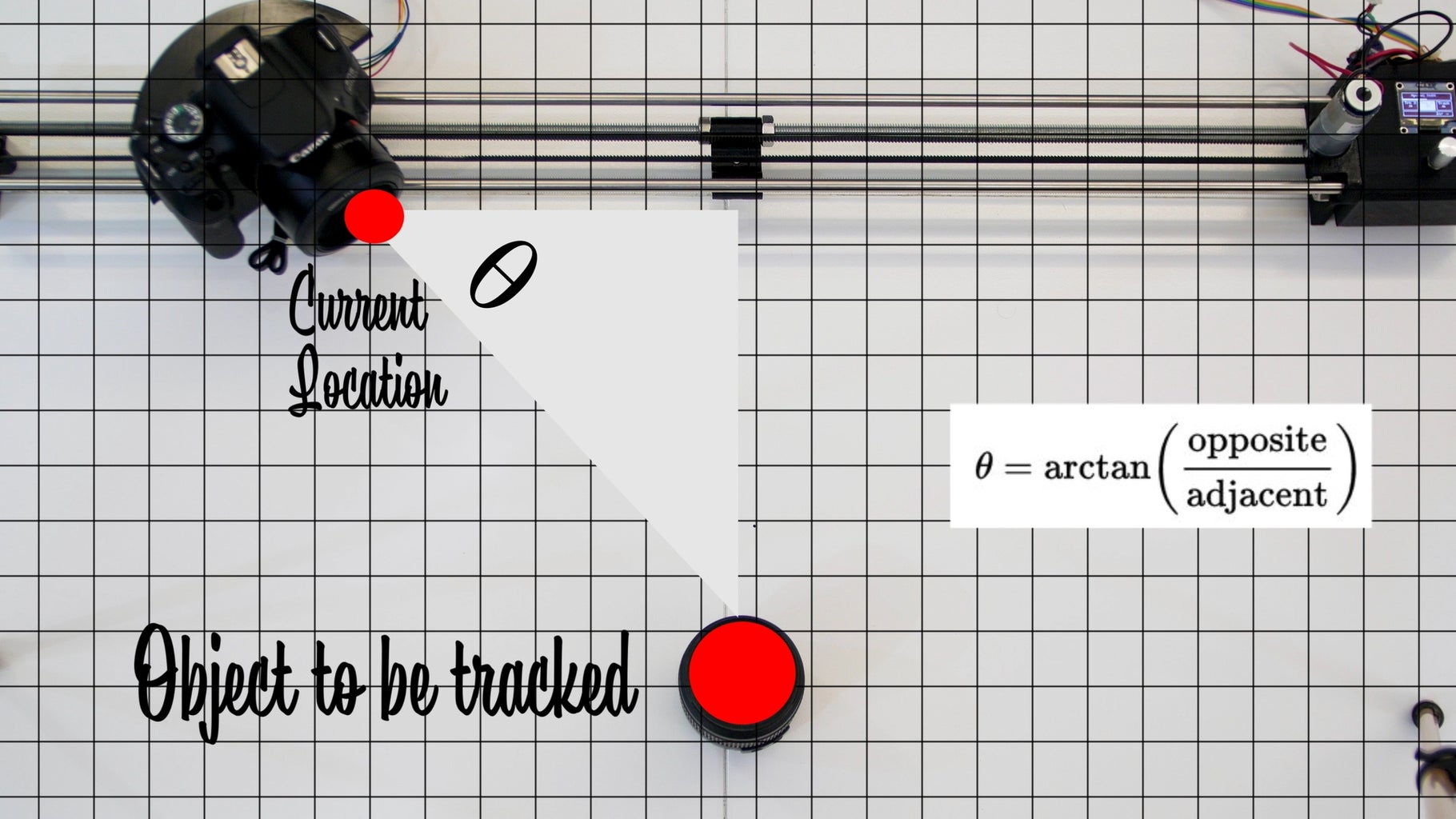
Next let’s talk about the rotational tracking element. This part seems very complex to integrate, but it is actually rather simple. The implementation for this is under the ‘motor()’ function inside my Arduino code. The first step is to make a 2 dimensional grid and decided where the object you want to track is placed. Based on that you can draw a triangle to your current location. You can get your current location from the encoder value of the motor. If you wish to configure the position of the object being tracked in cm/mm, you will need to translate your encoder value to a cm/mm value. This can simply be done by moving the camera slider 1 cm and measuring the increase in encoder value. You can input this value at the top of the code under the encoder_mm variable.
Moving on, now we will use the inverse tangent function to get the angle the camera must be facing to point at your object. The inverse tangent takes in the opposite and adjacent side of the triangle. The opposite side of the triangle never changes as it is the y distance from your slider to the object. The adjacent side of the camera slider does change however. This adjacent side can be calculated by taking the object’s x position and subtracting your current position from it. As the slider moves through its range of motion, it will keep updating the Arduino on the encoder value. The Arduino will repeatedly convert this encoder value to a cm/mm x positional value and then calculate the adjacent side length, and finally calculate the angle the camera needs to be facing at all times to point at the object.
Now that our Arduino is dynamically processing the camera angle, we can tackle converting this angle to a positional value for the rotational motor to move to. This brings us to the RoboClaw's biggest feature for this project. By giving the Roboclaw a position value, It can essentially make a DC brushed motor behave like a servo. Except unlike a servo, our motor has tons more torque, much higher accuracy and can also spin 360 Degrees.
The Arduino code to move the Roboclaw to a certain position is as follows:
roboclaw.SpeedAccelDeccelPositionM1(address, ‘speed’ , ‘acceleration’ , ‘deceleration’, ‘position you want to go to’,1);
To tune the positional value of the motor to correspond with your camera angle, you will need to manually move the camera plate 180 degrees. Next see how much the encoder value has changed from moving the camera plate from 0 degrees to 180 degrees. This gives you your encoder range. You can input this range in the motor function that maps the Arduino's camera angle to a positional value. This is also commented in the code so it should be easy to find *****
The RoboClaw also gave me the ability to tune other factors such as acceleration, deceleration and PID values. This further allowed me to smoothen the rotational axis movement especially when the angle changes were tiny and added jerks without high ‘D’ PID value. You can also auto-tune your PID values via the Roboclaw’s desktop app.
Step 4: Operating the Camera Slider
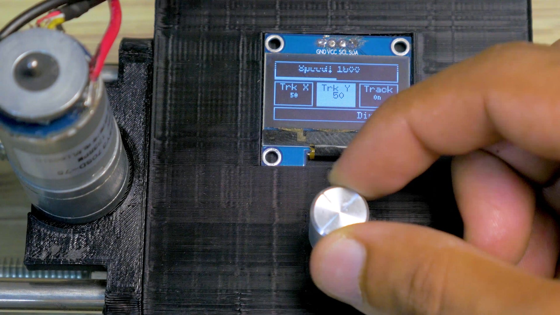
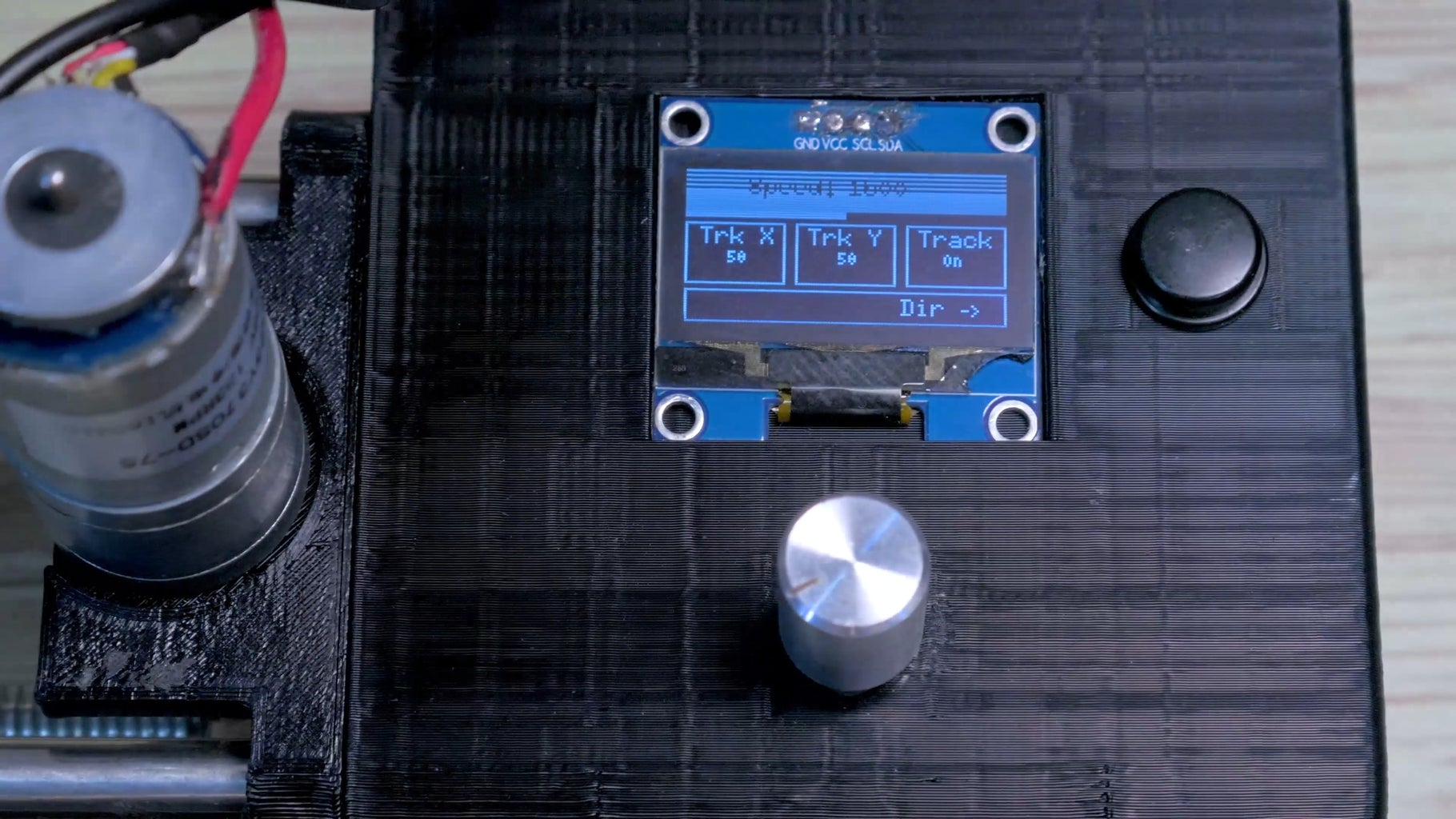
Now we come to the fun part, operating the slider The menu has 4 main tabs. The top tab is dedicated to speed control. The middle row of the menu contains tabs to configure the tracked object’s X & Y position in mm, and also configure if we want the slider to rotate and track our object or just do a simple sliding movement without rotation. Twisting the rotary encoder allows us to navigate the different options of the menus. To configure any of the options, navigate to the option and press the rotary encoder. Once pressed, rotating the rotary encoder will change the value of the highlighted sub-menu rather than scrubbing through the menu. Once you have reached your desired value, you can click the rotary encoder again. Now you are back to the main menu and can navigate between the different tabs. Once you are ready, simply press the go button next to the screen and the slider does its things!
Do make sure that once you are done using the camera slider, that the camera is in the ‘home’ position: the side of the slider it started on. The reason for this is that the motor encoder isn’t an absolute encoder meaning that the Roboclaw/Arduino can’t tell where the encoder is. They can only tell how much the encoder has changed since it was last powered on. This means that when you power off your camera slider, the slider will ‘forget’ the slider position and reset the encoder to a 0. Therefore, if you power off your slider on the other side, when you power it on, the slider will try to move further than the edge and crash into the slider wall. This encoder behavior is also why the camera resets its rotation angle after every camera slide movement. The rotational axis is also protecting itself from crashing into the end of its range of motion.
You could fix this by adding end-stops and a homing procedure when you boot up. This is what 3d printers use.
Step 5: Final Thoughts + Future Improvements
I strongly recommend that every builder make their own versions of this slider rather than build the exact same slider. Tweaking my design will allow you to build your slider to your exact specifications while also better understanding how the electronics & code work.
I made the code as readable and configurable as possible so you can tweak/calibrate the different code variables for your slider specifications. The code is also fully built around functions so if you want to copy/tweak/ rewrite certain behaviors of the slider, you don’t need to reverse engineer and rework the entire code but rather just the parts you want to edit.
Finally, if I made a version 2.0, here are some improvements I would make
- Higher gear ratio for the rotational axis motor. A higher gearing ratio means I can make more precise small moves. This is especially critical when the camera is far away from your object and your camera angle is changing very slowly. Currently, my motor isn’t geared too high and it can result in slightly jerky movement when the camera slider runs too slowly or when there is very little rotational angle change. Adding a high ‘D’ PID value has helped me get rid of this but has come at the cost of slightly lower object tracking accuracy.
- Modular length. This is a far-fetched goal, but I would love for the camera slider to be modular in length meaning that you can easily attach longer lengths of track for the camera to slide on. This is quite difficult since one will perfectly have to align both tracks and figure out how to have the belt system work. Nevertheless, it would be a cool upgrade!
- Custom movement Keyframing. I would love to introduce the concept of keyframed movements into this camera slider. Keyframing is a technique very commonly used in video & audio production. It would enable non- linear camera movements where the camera goes to a position, waits, then moves to another position at a different speed, waits, then goes to a third position etc.
- Bluetooth/ wireless phone control. It would be really cool to be able to configure the camera slider’s parameters wirelessly and be able to deploy the camera slider in hard to access locations. The phone app could also open up opportunities to integrate keyframing as mentioned in the last paragraph.
That's it for this tutorial. Feel free to drop any questions down in the comments section below.
For more content & electronics tutorials you can also check out my YouTube channel here.

Participated in the
Arduino Contest 2019


