

Introduction: OpenVFD: 6-Digit IV-11 VFD Tube Clock


![The NerdClock: An RGB Binary Clock [Arduino Software]](https://content.instructables.com/FJW/FFQM/IF2DEHPA/FJWFFQMIF2DEHPA.png?auto=webp&crop=1%3A1&frame=1&width=130)

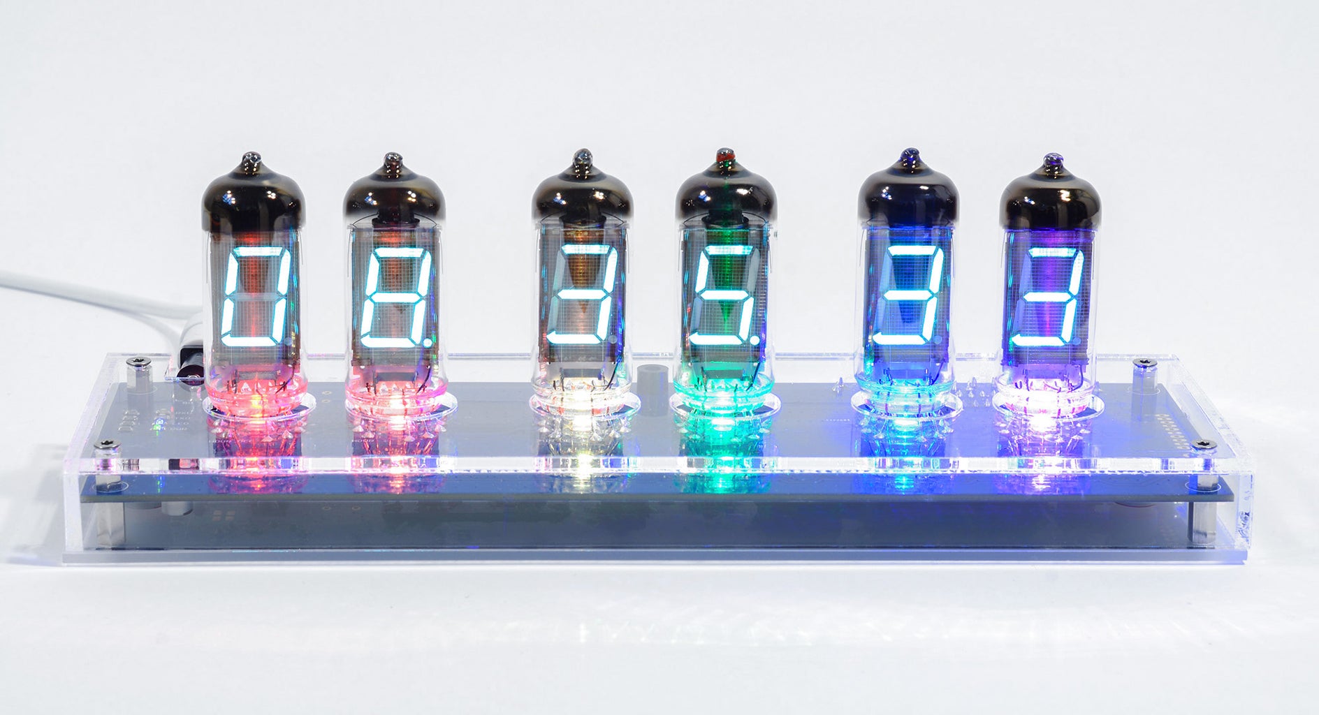
Introducing OpenVFD - the colorful VFD tube clock with light effects that make the clock dance, glow or turn into a rainbow.
I'm here to share my result of creating my own dream clock with you. A computer controllable, colorfully illuminated 6-digit clock utilizing vintage Soviet IV-11 vacuum tubes.
Entirely programmed in Arduino C code, OpenVFD implements a complete Arduino Uno USB connected platform to make it compatible and easy for everyone to understand, take apart, expand and improve!
About this Instructable
The Instructable shows you what makes my VFD tube clock work and I will take you through the process of turning some tubes, parts and a bunch of code lines into a glowing tube clock. It's great and easy to follow this Instructable if you have some basic electronics knowledge already, but don't worry if not. I'll do my very best to keep everything short and simple. Here is a little TOC:
- Introduction: The Concept
- Introduction: A Little BOM
- Fundamentals: Getting to Know IV-11
- Fundamentals: Generating the Right Voltage Levels
- Fundamentals: Gaining Control - A Discrete Approach
- Fundamentals: Gaining Control - The Integrated Solution
- Fundamentals: Interfacing the Microcontroller
- Adding Functionality: The Real Time Clock - DS1307 Vs DS3231
- Adding Functionality: Light Up the Clock
- Adding Functionality: Everything Else & Putting It All Together
- Building OpenVFD: The Circuit Board & Assembly
- Building OpenVFD: Acrylic Case
- Building OpenVFD: Make It Shine!
- Fluorescence by The VFD Collective
- Appendix: OpenVFD Software
Also feel free to check out the commercial version of OpenVFD: Fluorescence by The VFD Collective. If you find this Instructable useful, get your own clock by supporting the project on Kickstarter while I'm setting up the store of thevfdcollective.com!
Step 1: Introduction: the Concept


So what is a VFD?
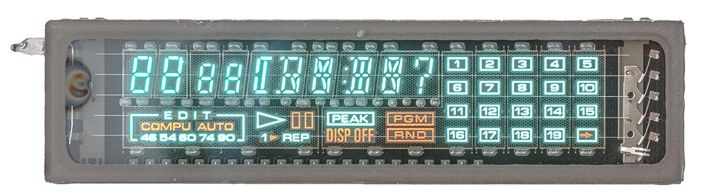
Meet an old friend! The VFD (vacuum fluorescent display), a very special vacuum tube developed in the 60s.
They glow in a crisp, futuristic teal color with remarkable, distinctive brightness and made it into calculators, stereos, car speedometers, cash registers through all the years. If you are curious, just like me, here is another Instructable by me if you would like to check out how the display works in theory.
As for the OpenVFD clock, I'm using old Russian so called "IV-11" tubes. Back then, they were chained together and made up the display of large calculators. Many of these tubes were produced, making them easy to obtain, even today.
What is the philosophy behind OpenVFD?
I wanted to recreate the VFD clock with most beautiful colors to see how colorful time can be. An IV-11 clock with tubes of uncompromising brightness, empathized by individually controllable little LED lights. Covered by a minimalistic, precisely cut acrylic glass, every color is diffused, reflected and fractioned when they reach the acrylic surface or the glass of the tubes. They create the vibrant mood, the peaceful ambient light or the perfect party moment when dancing to music!
Step 2: Introduction: a Little BOM
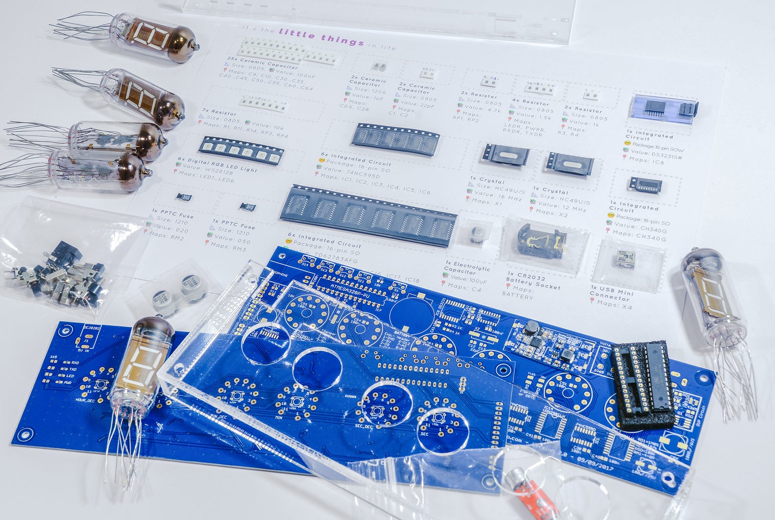
The parts you'll need for building the clock will heavily depend on how you want to build it. Just playing around, building a prototype clock with strip grid or maybe even a product ready for production. Here's a little BOM that gives you the feel of what you'll need if you'd like to build your clock interactively with this Instructable:
- Arduino Uno R3
- 6x IV-11 VFD Tube
- 1x Buck converter (e.g. LM2596 module)
- 1x Boost converter (e.g. XL6009 module)
- Both modules can be replaced by one OpenVFD EcoPower Module specifically designed for driving 6x IV-11 tubes!
- 6x 74HC595N 8-bit shift register
- 6x UDN2981A or TD62783APG 8-channel source driver
- DS1307 or DS3231 RTC clock module
- 4x tactile switches
- 4x 10 kΩ resistors
- 6x WS2812B RGB addressable LEDs (Adafruit NeoPixel)
- Electret microphone module (I use an amplified one with MAX9812)
- you can never have enough buffer capacitors (100 nF)
Ready to go? Let's start with the fundamentals!
Step 3: Fundamentals: Getting to Know IV-11


It all begins with this old Russian IV-11 tube. How do we light up the tube? More specifically, what kind of voltages do we need to turn a segment off? And what about turning on a segment? What is the pin layout of the tube?
Let's answer the questions by looking at the pinout diagram above.
- Pin 1 and 11 belong to the heater (cathode). Either pin can be tied to ground (0V) and the other one receives the cathode voltage of around 1.5 volts. The latter voltage needs to be on all the time to make segments glow
- Pin 2 is the grid pin. Giving this pin 30V (anode voltage) enables the display
- All the other pins (pin 3 to pin 10) are anode pins for the segments called 'a' to 'g'. 30V will turn the segment on, 0V will turn it off. It's really that simple.
A prehistoric drawing found in this datasheet illustrates the tube as its schematic symbol. If you're somehow familiar with tubes you'll surely notice that the IV-11 is just a fancy triode. In fact, that's what all VFD tubes and displays are. So isn't it insane that someone made a tube amp out of VFD displays?
Step 4: Fundamentals: Generating the Right Voltage Levels


Now that we've found out what voltage levels our VFD tube needs to work properly, it's time to make sure that we generate them from a base supply voltage, let's say 5V. (5V's just the most common voltage to work with as an electronics hobbyist).
The idea: Buck and boost converter!
Just two fancy ways to describe circuits that make a lower voltage out of a higher voltage and vice versa. We could use one of each since we have to get 1.65V from the so called buck and 30V from the boost converter. The chips we'll be using depend on one important question: How much current will our tube array draw? A glance at the datasheet gives you an idea of how much current parts of the tube will draw at maximum load. Let's do some simple math. We have six tubes. Each tube has 8 anodes, one grid, and one heater. A good guess would be:
Cathode voltage current requirement (worst case):
- 6 * Cathode current = 6 * 110 mA = 660 mA
Anode voltage current requirement (worst case):
- 6 * (6 * Working anode current + Grid current) = 6 * (6 * 5.0 mA + 17.0 mA) = 228 mA
This would be a total power dissipation of around 7 watts anode and about a watt for the cathode. That's some decent dissipation and the reason why we won't torture linear regulators for the step down path. For testing, take out the XL6009 step up and step down LM2596 module, and set the potentiometers so that you get the right voltage levels.
For my first PCB design, I've used LM2576-ADJ for step down and LM2577-ADJ for step up simply because they were available at my local store. You can do better and get one OpenVFD EcoPower Module specifically designed for driving 6x IV-11 tubes - but basically any IC fulfilling those requirements will work just fine.
Got the voltage levels right? You can now put the tubes on a breadboard and play with turning segments on and off. Can you tell which pin belongs to which segment and which pin the decimal dot is? Tried displaying all numbers 0 to 9, maybe even some letters?
Step 5: Fundamentals: Gaining Control - a Discrete Approach


Since you now know how your VFD displays the characters by applying the right volts to the anodes, it's time to do even more. So the controlling mind behind the VFDs won't be a person or some crackhead you hire who does un- and replugging segment voltages real fast, but a microcontroller switching in a highly precise manner. But there's one little issue that keeps us from connecting the tube segments to the microcontroller directly:
The typical microcontroller (TTL) switches between 0 and 5V, while 5V means a logical '1' or 'HIGH' and 0V a logical '0' or 'LOW'. Remember we need 30V and more than 15 mA at 30V? I mentioned the current because a microcontroller can only switch a very limited amount of current (typical: 20 mA @5V). Sometimes that's sufficient to switch a green LED but not a VFD segment. So we'll have to come up with a circuit that gives the desired 30V to our VFD segments when we use 'HIGH' to tell a segment to turn on and 0V to the segments when we go 'LOW'.
A Discrete Approach
But how exactly do we toggle the segments with just 5V? The initial circuit I came up with is, I believe, simple and intuitive. It builds upon an NPN-PNP bipolar transistor pair, where the NPN receives 0-5V in, and switches 30V over the PNP. See how it works:
- Say we want to turn a tube segment off. So we apply 0V to the control input. The base voltage is 0V, so the NPN transistor is turned off, right? That means no current can flow through the path with R2, and the PNP transistor gets pulled up to 30V (VDD) over R3. Because of this we know that our PNP won't turn on either, and our segment is off since it doesn't get any current
- Now let's see why 5V on 'CONTROL' will turn on the segment. With a positive voltage, Q1 will turn on. This makes R2 and R3 into a voltage divider where the base of Q2 will certainly receive a voltage (much) less than 30V. So Q2 will open up as well, switching 30V to the anode of the tube. The segment now lights up!
Together with port extending shift registers (I'll talk about them later), you can see the tube control prototype board with 48 of those NPN-PNP pairs on the picture above. I've shown this circuit to you since I believe that everyone has at least a few BC547 and BC557s lying around. So if you have some, don't hesitate to put this control circuit on breadboard using a few of them now!
Step 6: Fundamentals: Gaining Control - the Integrated Solution


If you're a bit familiar with soldering, you know that soldering more than 70 SMD transistors is no fun at all. So we have to modify our discrete circuit, moving towards higher integration. Simultaneously, I'm happy to tell you that we're getting closer to OpenVFD's final tube circuit.
The idea behind it is that we try to get a very similar NPN-PNP pair under the hood. Why? Because we still have to switch 30V to the segments. Found out that the UDN2981 8x TTL, so called high side switch is a good choice for this.
If that's on breadboard too, feel free to send TTL-level inputs to the UDN2981 you just got (TD62783 will do exactly the same thing). But be careful and don't short out any outputs. This will burn the internal transistors immediately since they have no protection at all.
Step 7: Fundamentals: Interfacing the Microcontroller


Awesome, we are almost done with fundamental stuff for the tube circuit. What you see in the picture is the completed tube circuit of OpenVFD as found in the final schematics.
And where's the magic? Right. All I did was to copy and paste the circuit in step 4 exactly six times, since we need six tubes. Now it's finally time to reveal the functionality of the 74HC595. Previously mentioned and seen, the 74HC595 is a shift register. We use it because the microcontroller only offers a very limited amount of I/O pins. Shift registers let you connect more stuff with just three pins: All of our data is shuttled through a serial pin into shift registers, controlling high side switches that we met before to turn the tube segments on and off.
Now if your tube circuit is sort of set up, get your microcontroller ready! We are going to microcontrol the six VFD tubes for the very first time. If you want to use an Arduino board, like I did, connect
- clock pin of the 74HC595 (pin 11), SCK to pin D2 of the Arduino Uno
- latch pin of the 74HC595 (pin 12), RCK to pin D3
- and serial data pin of the 74HC595 (pin 14 of the first shift register), SER to pin D4 of the Uno
Have some fun with the little block of code I've written for a test drive. It's just a simple and stupid counter which starts at zero and counts up to 999,999. The top Fritzing picture shows how the first 74HC595 is supposed to be connected. All output pins will go to the UDN2981 except for pin 9 (serial out), which has to be connected to serial in of the next 74HC595.
Attachments

Step 8: Adding Functionality: the Real Time Clock - DS1307 Vs DS3231

What else do we need for a VFD clock? Oh right... it's the clock. So finally we're adding a circuit that provides clock functionality. Our so called RTC (real time clock) is backed up with a battery so that the clock can tick on even if OpenVFD is turned off itself. That makes sense, right? Since we don't want to lose the time when turning on the next time. We choose between a DS1307 and a DS3231 module:
- The DS1307 is an affordable RTC solution, simple to control but with trade-off in accuracy depending on the crystal used - which is in general pretty inaccurate due to temperature change. I had situations where the DS1307 was a minute or more off after a day. That wouldn't work in a commercial product at all
- Luckily, the DS1307 module can easily be (almost) drop-in replaced by a DS3231 module. The DS3231 is a RTC with a TCXO (temperature compensated crystal oscillator) ensuring jaw-dropping accuracy of less than a minute error per year
After all, which one you want depends on how accurate you want it to be. Both are tested to be both pin and source code compatible to the OpenVFD schematics and firmware (software). We connect the I2C interface of the DS1307/DS3231 module to the I2C pins of Arduino (SDA -> SDA, SCL -> SCL).
Step 9: Adding Functionality: Light Up the Clock


Now let's add the most memorable characteristic of the OpenVFD clock: The LEDs that light up the tubes to create the effects and moods that we all love. It begins by finding the right RGB LED that is reliable and bright. Why RGB? Here's how beautiful colors work: We combine the three colors of RGB (red, green and blue) to get new colors. So, for instance, purple is just blue and red mixed together.
Meet the WS2812B digital LED. This LED acts like a shift register and is controlled by shuttling data through one single data pin.
What makes the WS2812B really lovely is that the exact same LED is found in NeoPixel by Adafruit. Even though the OpenVFD firmware does not rely on any Adafruit libraries (but on work done in this wonderful Instructable), Adafruit still provides brilliant documentation on this LED that help when working with them. Take a look at the connection diagram. OpenVFD chained up six WS2812Bs to light up the six tubes individually.
Just like the traditional Arduino-Hello-World uses Pin 13 for the 'blink' program, our LEDs are connected serially to Pin 13! Don't worry if they are SMD and not-so-breadboard-friendly. Something like this Adafruit breakout board will solve the problem . Or create a breakout board yourself!
Step 10: Adding Functionality: Everything Else & Putting It All Together


For the time OpenVFD is not connected to a PC, four tactile switches are used to set time, play with colors and do much more. The firmware OpenVFD makes them reacting to short and long presses.
A microphone module (MAX9812) makes your VFD clock dance to the tunes you enjoy. It measures sound as variations in air pressure and sends corresponding electric signals that are then evaluated by the microcontroller. Temperature measurement is done by a LM35 sensor that converts temperature into voltage levels. Our microcontroller translates this back to a temperature value that we all understand. While the RTC gets ridiculously accurate using DS3231, both LM35 and DS18B20 are somewhat like the German weather: moody.
---
And we're done with the complete VFD clock circuit design. You can download and see the complete prototyping circuit diagram below. If you got it on breadboard or prototype board by now, we're totally ready to upload the OpenVFD firmware to your microcontroller.
The latest firmware of OpenVFD is available on GitHub . When compiling, make sure the libraries RTClib, Wire and digitalWriteFast are ready. These are the only dependencies of OpenVFD. Everything about how the firmware works in detail is explained here.
Attachments

Step 11: Building OpenVFD: the Circuit Board & Assembly


For the final prototype, I've designed a printed circuit board (PCB) which holds and interconnects the components. The design is as simple as it gets. It contains screw holes for a case mount, features buttons and plugs to be mounted to the back side of the clock.
Assembly begins from the circuit part with the lowest part profiles. In the last step, six of the IV-11 tubes are added to OpenVFD and we're done.
I decided not to publish PCB files as it is not suitable for home etching (hundreds of vias and thin traces). But the good news is that I will be working on a home-etching friendly PCB version that everyone can try out at home in the future. In the meantime... Why don't you design your very own PCB? I promise it's fun!
Step 12: Building OpenVFD: Acrylic Case


OpenVFD is about light and passion. To amplify this, the clock is designed to have its transparent enclosure made possible by acrylic. The aim is absolute simplicity at maximum color experience.
---
For your own clock, simply measure and create a case yourself using a laser cutter. I'm lucky to live next to FabLab Berlin, a place where crazy creative minds meet up. They got all the right tools. Otherwise, I'm pretty sure that there are a lot of services online that offer laser cutting.
Step 13: Building OpenVFD: Make It Shine!


When mounting the acrylic case and everything is done, it's time to light up the clock!
- Find some exclusive place for the clock. Glass surfaces seem pretty ideal
- Show it off to your friends. Celebrate how freakin' amazing you are!
And say thanks to me by voting for this Instructable, thank you for reading! <3
Step 14: Fluorescence by the VFD Collective


If my Instructable has inspired you to build your own VFD clock or you would like to have a complete one yourself, I'm excited to introduce Fluorescence by The VFD Collective to you. FLUORESCENCE is the commercial product based on the OpenVFD software and platform, using the second revision circuit board.
Feel free to check out www.thevfdcollective.com and build your own VFD clock using the DIY kit!
Technically, FLUORESCENCE builds upon all the strengths of OpenVFD like a flicker free display, full brightness and improves highly on design, energy efficiency and circuit protection. You can download the block diagram as well as the schematics of FLUORESCENCE right here:
Attachments
Step 15: Appendix: OpenVFD Software


The stars of the appendix: OpenVFD Controller (myOpenVFD) and the firmware. With myOpenVFD, a simple to use Windows app that sends data over USB to the clock, you'll be able to
- Set the OpenVFD time by synchronizing with your computer's clock
- Set individual color for an LED in OpenVFD or choose a predefined pattern
- Send some funny random messages to the clock display
- Check the OpenVFD firmware version, check for updates Update or write new firmware to OpenVFD
OpenVFD Firmware is the software that controls and coordinates how things work on the clock. Written in Arduino C/C++ it sends clock or any data information to the tubes, sets different LED brightness levels, retrieves sensor data (temperature, sound) and gets in sync with the real time clock. It's just a single .ino file, handy to compile yourself.
Click here to see how the OpenVFD firmware works in detail with every function taken apart. That might be helpful if you want to write your modifications to the firmware!
Both myOpenVFD and the firmware can be downloaded from The VFD Collective. Also, find The VFD Collective on GitHub!

Runner Up in the
LED Contest 2017

Participated in the
Arduino Contest 2017

Participated in the
Epilog Challenge 9


