

Introduction: Perler LED Nightlight


My family loves to craft with Perler beads. I have seen other people's Perler nightlights and like the box framed look. I want to share how I went about making a Perler nightlight.
I used regular 5mm LEDs instead of LED strips to make the nightlight low power and be able to run off batteries.
Materials
- Float Frame (from Target)
- Thin wood (1/8" plywood)
- Screws (size #4)
- 5mm LEDs (colors to match your artwork)
- 3mm Craft foam
- Velcro
- Perler beads
- Momentary push button (Off-momentarily On)
- USB cable
- Battery pack (any phone recharging pack)
- 12AWG stranded wire
- 24AWG hookup wire
- AT43 DC 3-12V delay circuit module (available of eBay)
- CLG2N3 LED driver (available from DigiKey)
- DC-DC boost step up module (available off eBay)
- Black spray paint
- Flat white spray paint
Tools
- Soldering iron
- Glue gun
- Screw driver
- Hobby knife
Step 1: Bead Your Perler Pattern


Choose a Pattern or make one up. Make sure your pattern will display nicely within the frame. The following are tips on crafting your pattern should you need help.
Start with a subject that fits within the frame. My daughter wanted Minecraft Steve.
Next make a paper template of the frame. The viewable area is cutout and the outer line is the area available within the frame.
Use the template to position your subject.
Add beads to the corners to mark the corners of the viewable area.
Fill in the pattern up to your markers and then extra as needed to fully fill up the frame internally. This way you won't have a gap between your artwork and the trim of the front frame.
Melt the beads together. You will want to close the bead holes on at least one side completely for this project. I tried with open beads but you do not see the pattern illuminate. Instead, you just see the LED lights right through the Perler bead holes. I just completely melted one side as I like the look of the circle outlines.
Step 2: Prepare Frame Back


Remove the hardware (tabs, screws, mounting brackets) on the back of the frame. Remove the spacer and glass panes from the frame.
Use a hobby knife to clean up the screw holes as they tend to have excess plastic protruding out. The protruding plastic will interfere with the backboard placement and you don't want that.
Step 3: Cut Backboard


Place the frame on the plywood with the front side up.
Trace the outer edge and the inner edge of the frame onto the plywood. The inner tracing will help guide where to place the screw holes. I marked the outer outline with "cut" so I would not inadvertently cut along the inner outline.
Cut out the backboard and don't worry too much about trying to clean up the outer edge as you will trim it down later.
Step 4: Place Backboard Screws


Mark the backboard for screw your screw holes. I arbitrarily chose 4cm (short edge) and 5cm (long edge) from the corners. I chose 3mm from the inner outline towards the outer edge because that seemed like a safe close enough distance to the inner edge. You don't want the screw to be too close to the outer edge because the you will trim the backboard and the screw hole may be too close to the outer backboard edge.
Mark the backboard with 'Top' and 'Bottom' to help with assembly later. We are human and do not have precise drilling skills (well maybe some of you do, but I do not).
Only drill a pilot hole at your marks for now as you will use the backboard as a drilling template on the frame.
Note: If you noticed I flipped my backboard, that is because my board warped after cutting. I rather have the concave part facing the back of the frame as that will be easier to screw down. I also added a third screw to that side to hold the concave part down. Probably best to use a craft birch plywood as they tend not to warp. I used a cheapy 3ply, oh well.
Step 5: Place Frame Backboard Screws


Note which is the top and bottom of the frame. I used the short edge that had the frame mounting hardware as the top.
Place the backboard on the back of the frame. Align the backboard edges with the frame.
Clamp the backboard to the frame. Use light clamping pressure since the frame is made of plastic. I clamped along each edge so that the clamps act as table legs. This made drilling a lot easier than if only two clamps were used as the frame would rest at an angle.
Use the holes in the backboard as a template to drill pilot holes into the frame.
Unclamp the backboard when you have drilled all the pilot holes.
Use a screw to kind of tap the screw holes. When you remove the screw, you will sometimes be left with plastic protruding from the screw hole. Clean up the hole as you did before.
Step 6: Place Power Cable and Power Button


Place your USB cable and power button on the backboard. Move them around to where you feel is the best place. Make sure the power button is set in enough that it will not be hindered by the frame.
Note: I cut off the micro USB connection side of the cable as that will not be needed. Just drill a hole big enough for the cable.
Mark the cable and power button spots and drill holes for them. Make sure to test fit and then remove them for the next step.
Step 7: Trim Backboard


Countersink your screw holes if you used countersink screws.
Screw the backboard onto the back of the frame. Chances are good that you will have some of the board protruding from the edge of the frame. Draw an outline of the frame on the backboard.
Remove the backboard from the frame. Draw an outline 2mm in from the new outer outline. Mark the outside of this outline to cut. I put 'X's to help me know what needs to removed.
Trim off of the excess.
Step 8: Paint It Black


I see a plain wood board and want to paint it black.
Sand the front and back of the backboard to remove splinters and prepare for painting. Your choice of how much you want to prep the backboard for painting. I stopped at 120 grit as the back will hardly be looked at.
Mount the backboard onto a stick and spray paint the back black to match the frame. Don't forget the outer edges too. After the first coat, I put the screws in the holes so that the next coats will paint the heads black. Not really needed because the back will be hardly looked at, but I wanted to keep the back uniformly black.
Let the paint dry for a day or so after the final coat and remove the backboard pfrom your painting stick.
Step 9: Paint Inside White


Painting the inside backboard and the inside of frame flat white will help reflect light out.
Screw the backboard back onto your painting stick with the inside facing out. Use painters tape to mask the outer edge, cable hole, and power button hole to prevent overspray from ruining your outer black coat.
Use painters tape on the on the outer faces of frame. Make sure to tape the inside part of the front of the frame (edge outside of frame glass pane). Take care that you tape the corners well. I like to put little strips on the corners first, that way you can be sure that there is no gap. Tape folded into the corner can sometimes lift creating a gap.
Spray paint the inside of the backboard and frame with flat white paint. Flat white will reflect better than glossy (according to the internet).
Let the paint dry a day or two after the final coat. Remove the backboard from the painting stick.
Step 10: Set DC-DC Boost Step Up Voltage


Attach your battery with a USB cable or solder wires directly to the DC-DC boost step up module. Check the voltage on the input just to make sure your battery is charged and at or around 5V.
Turn the potentiometer clockwise to increase the output voltage and counterclockwise decrease the output voltage.
I planned to string 10 LEDs together. I raised the output voltage to 24V as a starting point. Technically would need just around 20V (10 LEDs x ~2.0Vf) but you can get the lights just a wee bit brighter with a little bit more voltage even though the CL2N3-G is a constant current driver (push the driver to 22mA instead of just 20mA).
Step 11: Test LED Lights


Use a breadboard and string up LEDs and test the CL2N3-G driver with your DC-DC boost step up module. Use the breadboard to give you an idea of how much light you want. Adjust the DC-DC boost step up module so that the driver does not have to work too hard. I lowered the output voltage to 22 volts as the brightness for 10 LEDs was the same as 24 volts.
I first stringed up 10 LEDs together and noticed that the lights were super bright. I added one more LED and the brightness was the same. I added the 12th LED and the LEDs dimmed considerably. I stuck with 10 LEDs per driver as 20 LEDs total divides evenly into 4 rows.
Since a bottom portion of the Perler beads are green, I made a row of green LEDs. Also, the reason for the green row is that I learned something new. Red light doesn't pass through green filter since green filters out red leaving only blue and yellow. So the bottom of the Perler beads was very dark.
Step 12: Connect LEDs Together


Arrange the LEDs on the backboard to get an idea of the spacing between the LEDs. Measure the distance between the LEDs.
Cut a piece of 12AWG stranded wire as long enough to reach from one LED end to the other. Pull as much strands of wire as your rows individually from the 12AWG wire you just cut. Straighten the individual strands as much as possible.
Bend the legs of the LEDs 90 degrees outward from each other.
Tin the legs of the LEDs and the strands of wire.
Solder the legs of an LED to the center of the strand. Make sure you solder the LEDs correctly oriented with the cathode of one facing the anode of the other. If you forgot which leg was which, look at the LED and you will see two metal plates, one will be bigger than the other. Look at an unbent LED to see which plate connects to the anode and cathode.
Right now the LED has the legs shorted, don't worry about that as you will cut the shorting wire later. Solder the rest of the LEDs in place correctly spaced apart. Use this first string of LEDs as template for the rest of strings.
Use helping hands to hold the first LED string and another strand of wire right next to it. Solder the second set of LEDs at the same positions of the first strand of LEDs. Repeat for the rest of the rows.
Test place your LED strings on the backboard to see if you like it.
Finally cut the wire in between the anode and cathode of each LED. If you are lazy like me, just cut close to one leg and bend the wire back toward the other leg, this save time trying to pick up the tiny pieces of wire you cut off.
Step 13: Mount and Wire Electronics


Bend the end legs of the LED strings so that you can rest the string with LEDs pointing up. Place them on the backboard along with the AT43 delay timer and DC-DC boost step up module.
Strip about a centimeter off the outer cable casing of the USB cable to expose the individual wires. Strip off about 2mm of insulation off the power wires (usually red and black). Tin the exposed wire ends.
Attach your power button and pull the USB cable end through the hole of the backboard. Hot glue the USB cable in place from the inside to prevent the cable from pulling out.
Hot glue the LED strings into place. I had to reroute the LED strings around the USB cable and power button. Use left over strands of wire to connect the LED rows together. Solder on the CL2N3-G to the LED strings.
Solder wires from the DC-DC boost step up module positive terminal to the CL2N3-G and ground of the module to the anode end of the LED string. Now is a good time to apply power to the boost module to make sure the lights are working properly.
Solder a wire from one terminal of the power button to the positive power of the USB cable. Solder another wire from the USB negative to the ground input of the DC-DC boost step up module.
Use a 4P DuPont connector to make connections to the AT43 timer easier, if not, just solder the wires in place. Connect the first pin of the AT43 timer to the same terminal on the power button connected to the USB cable. Connect the second pin of the AT43 timer to the positive input of the DC-DC boost step up module. Connect the third pin to the other terminal on the power button. Connect the last pin to the ground of the step up module.
Attach the battery and test that the lights turn on and automatically off. As long as you haven't touched the AT43 timer potentiometer, the lights will be on for just about a second.
Step 14: Adjust Timer

The AT43 timer is adjustable from 1 second to about 20.5 hours. There are two jumpers on the side of the board. The jumper closest to the 4 connection pins controls the time range and the other if the output is initially high or low first.
If you are setting the time relatively long, say 30 minutes, not practical to turn the potentiometer and wait around to see how long the lights stay on. You can get a good enough rough estimate with a bit of math without having to wait a long time for each adjustment..
The timer has two ranges 1 to 290 seconds and 256 seconds to 20.5 hours. The jumper is then just some sort of multiplier.
If you want 30 minutes, convert that into seconds.
30 minutes = 1,800 seconds
Next convert the longer time range into seconds.
20.5 hours = 73,800 seconds
Offset the range and the 30 minutes by 256 seconds since that is where the range starts.
73,800 seconds - 256 seconds = 73,544 seconds
1,800 seconds - 256 seconds = 1,544 seconds
Next calculate the ratio of 30 minutes of the long range to the short range.
1,544 seconds / 73,544 seconds = X seconds / 290 seconds
Solve for X and you get roughly 6.08 seconds.
(1,544 seconds / 73,544 seconds) * 290 seconds = 6.08...... seconds.
Adjust the lights on the short range (jumper on pins 1 and 2) for 6 seconds. Turning the potentiometer clockwise increases time and counterclockwise decreases time.
When you have 6 seconds set, move the timer jumper to the longer range (pins 2 and 3).
Test the timer and your lights should stay on close to 30 minutes.
Step 15: Mount Perler Picture


Clean the frame's glass plane (you only need one even though the frame comes with two). You don't want fingerprints showing on the inside.
Place the Perler artwork in. I like to have the bead circles face out. This enhances pixilation to me.
Cut strips of 3mm craft foam about 9mm wide and to length of the inner width and height. Wedge the foam in the molded channel along the inside of the frame. This will hold the Peler artwork in place and snug up against the glass.
Step 16: Mount Battery Pack


Screw the backboard onto the frame.
Use Velcro to mount the battery pack to the back of the backboard.
Put the loop part on the battery.
Connect the battery to the USB cable.
Place the hook part on the loop part that is attached to the battery.
Remove the backing of the hook part and place the battery onto the backboard. Place the battery in a spot not too close and not too far from the USB cable.
Step 17: Enjoy Your Nightlight


Place the nightlight somewhere safe since the frame uses glass (alternatively, you could cut out a piece of acrylic if you are afraid of the nightlight breaking from a fall).
Push the power button and marvel at your creation.
My daughter named the nightlight "Sunburned Steve's Sunset" since I used red LEDs and Minecraft Steve glows red.
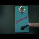
Shown is another nightlight with just green LEDs for Yoshi.
Thank you for reading.

Participated in the
Make it Glow Contest 2016

Participated in the
Homemade Gifts Contest 2016


