Introduction: Jumboinga - the Jumping Boinging Game


Simple roulette/wheel type game using a door stop spring to spin the wheel. Uses the Adafruit Circuit Playground Express (CPX) with a piezoelectric sensor and a door stop spring. User pulls back on the door stop spring and lets go (or knocks the game board really hard) to start the wheel moving (light going around the NeoPixel ring of the CPX). Wheel spin determined by how strong and long the spring vibrates.
Step 1: Gather Supplies and Tools.
The game is fairly simple to build as there are not much components to it. Tools wise you don't need much either.
Supplies
- Circuit Playground Express
- Door stop spring
- 3 x AAA battery holder with power switch and JST female connector
- Piezoelectric sensor
- 3.3V Zener diode
- 1M Ohm resistor
- 4-40 3/4" screws * 4
- 4-40 nuts
- #4 3/4" wood screws * 2
- #4 3/8" sheet metal screw
- Ring terminals * 2 (not sure what the size is but its small and sized to fit 4-40 screws)
- 3-1/2" x 1/2" x 24" wood craft board
- 1-1/2" x 1/2" x 24" wood craft board
- Wood glue
- Wire
Tools and Other Stuff
- Saw
- Drill
- Drill bits
- Screw driver
- Sand paper
- Soldering iron
- Solder
- Helping hands
- Wire stripper
- Wire clippers
Step 2: Cut Wood Pieces to Length.


Measure and cut the wooden craft boards into the following pieces:
- 3-1/2" x 1/2" x 7" * 1 piece
- 1-1/2" x 1/2" x 7" * 2 pieces
- 1-1/2" x 1/2" x 1/4" * 1 piece
The single 3-1/2" x 1/2" x 7" piece will be for the top of the game.
The two 1-1/2" x 1/2" x 7" pieces are for the legs of the top wood piece.
The single 1-1/2" x 1/2" x 1/4" piece will hold the piezo sensor against the top wood piece.
Step 3: Mark Top Center Line Length Wise.


Mark 1-3/4" on both ends of the 3-1/2" piece you cut in the previous step.
Draw a line from end to end using the marks.
Do the same on the other side of the board.
Step 4: Mark Placement of Door Spring Screw.


Mark 1" in from one end.
Use a center punch to indent the mark.
This will be a guide for other markings.
Step 5: Mark Holes for the Circuit Playground Express.


Place the Circuit Playground Express flush to the edge of the board opposite side of the door spring screw mark.
Face the USB port toward the edge so that you can connect a USB cable to board.
Mark holes for screws that will go in the following:
- A3
- A4
- GND (immediate left of the power connector)
- Vout
You could just use A3 and GND but I added A4 and Vout to have a symmetrical screw placement. I think that looks better than just 2 not really across each other.
Also a good idea to label your marks.
Step 6: Mark Spot for Battery Power Cable.


Place the Circuit Playground Express back on the top board.
Make a mark 1/4" away from the power connector.
Use a center punch to indent the mark you just made.
Also center punch the marks you made for the Circuit Playground Express.
Step 7: Label the Top Board.


Label the top board to make it easier to follow the upcoming steps.
Label the edge of the board that has the Circuit Playground Express as Top and this side of the board as Front.
Label the opposite edge as bottom (the picture has a mistake in that I labeled it top, it should say Front).
Step 8: Mark and Drill Piezo Holder Screw Holes.


Make two marks in the middle on both ends 1/4" in from the edge on the 1/2" side.
Use a hole punch to indent the marks.
Use a 1/8" bit to drill holes in the marks you made.
Step 9: Drill Circuit Playground Express Holes.


Use a 9/64" drill bit to drill the four marks made earlier to hold the Circuit Playground Express.
Test fit the board with 4-40 screws. My drilling was not precise to I just wiggled the drill a bit to enlarge the holes slightly.
Step 10: Drill Door Spring Screw Pilot Hole.


Use 5/64" bit to drill the pilot hole for the door spring screw.
Keep the bit in the drill as we will use it to drill a pilot hole for the battery connector.
Step 11: Drill Battery Connector Hole.


Drill a pilot hole with the 5/64" you used in the previous step at the battery hole connector mark.
Use progressively larger size bits till you get to 1/4" to prevent tearing out big chunks of wood.
Test fit that the battery connector fits through the 1/4" hole you made. If the hole is too small, either wiggle the bit a little to enlarge the hole slightly or go to the next reasonably larger size bit.
Step 12: Drill Piezo Holder Pilot Holes.


Mark a line 1" in from the bottom on the back side of the board.
Place wood screws through the 1/4" holder.
Eyeball center the of the board with the holder and line up the screws with the line you just made. Push the screws firmly to mark where to drill the pilot holes for the holder.
Use a 1/16" drill 3/8" deep into the board. Try not to drill all the way through else you will have ugly holes on the topside of the board. If you do, no biggie, you can use filler on the topside of the board.
Step 13: Sand the Boards.


Sand the boards to remove any large splinters. You don't need to sand to a super smooth finish, just enough to remove splinters.
Step 14: Test Fit Legs.


Test fit the legs of the board to the top board. Put a leg on each side. They should be able to stand on their own which will help when we glue and clamp the legs.
Step 15: Glue Legs to the Top Board.


Use wood glue to attach the legs to the top board.
Apply glue liberally to the edge of the leg board.
Place the leg onto the top board and hold firmly together.
Use a damp rag to wipe off the excess glue.
Repeat for the other leg board.
Step 16: Clamp Legs Together.


Use clamps to hold the legs in place while the glue dries.
Wait overnight for the glue to dry for full strength.
Step 17: Test Fit Door Spring.


Test fit the door spring hardware.
Use 3/8" #6 screw instead of the supplied screw with the door spring. The supplied screw is too long.
Screw the spring base to the front of the board. Check the back side to make sure the screw doesn't go all the way through.
Attach the spring to the base and give it a boing just for fun.
Remove the spring for now as putting the game together will be easier without the spring attached.
Step 18: Buld Clamping Circuit.


The piezo sensor can produce voltages way above the analog in 3.3V maximum of the Circuit Playground Express. Use a 3.3V Zener diode to clamp the voltages produced by the piezo sensor. I'll be honest, I do not fully understand enough to explain the role of the resistor, checkout this thread (Very basic resistor/piezo question) in the Arduino forum if you want to know more about it.
Place the resistor and diode as shown in the picture.
Bend one leg of the 1Meg Ohm resistor down toward the diode.
Wrap the resistor's leg around the diode's leg.
Repeat with the other leg of the resistor.
Step 19: Solder the Resistor and Diode Together.


Place the resistor and diode duo into a clamp or helping hands.
Solder the wrapped legs together.
Use a cutter and cut off excess parts of the legs.
Step 20: Solder Clamping Circuit to the Piezo Sensor.


Solder the clamping circuit to the piezo sensor with the cathode of the Zener towards the positive wire of the piezo. The cathode side of the Zener diode has a black band around it.
Step 21: Solder Wires to the Peizo Circuit.


We need to solder wires to the clamping circuit to reach the Circuit Playground Express. Use wires about 7" or longer in length.
Strip and tin one side the of wires. I like to strip off about a 1/4" of insulation, tin the wire, then cut off excess leaving about 1/8" of tinned wire.
Solder the wire to the clamping circuit.
Step 22: Trim Wires.


The wires from the previous step will be longer than needed. We will need to trim them to keep the wiring nice and tidy.
Place the whole circuit on the bottom side of the game with the piezo towards the bottom.
Measure enough wire with some slack from the piezo to the hole that leads to A3 for the positive wire and GND for the negative wire.
Cut off the excess wire.
Step 23: Optional: Cover Expose Leads.


Not a necessary step but you could use electrical tape to cover the exposed leads of the clamping circuit.
I did this before I realized hot glue would hold the wires to the board and cover the exposed leads at the same time.
If you don't like exposed leads go ahead and cover the circuit with tape.
Step 24: Attach Ring Terminals.


The wire I used was too small to crimp so I just soldered on the ring terminals to the wire. This should be okay since the wires will be stationary in the end and not need the flexibility that crimping gives.
Strip and tin the ends of the wire.
Tin the end of the terminal.
Solder the wire end into the terminal.
Repeat for the other wire.
Step 25: Mount Piezo Sensor.


Place the piezo sensor centered on the bottom of the board right under where the spring will be.
Put 3/4" #4 wood screws in the screw holes of the 1/4" holder wood piece.
Place the 1/4" holder over the piezo sensor.
Screw down the holder to the point the sensor cannot move freely.
Do not overtighten. You will know if you have the holder on too tight when you test the game as you will need a very strong vibration to trigger the game and not much range of vibration strengths.
Step 26: Mount the Circuit Playground Express.


Place the Circuit Playground Express on the top front side of the board.
Place 3/4" 4-40 screws in A3 and GND.
On the back side, connect the wires to their corresponding screws with the screw terminal. Connect positive to A3 and negative to GND.
Use a nut to hold the screw and ring terminal in place.
Place screws in the remaining two holes and use nuts on the backside to hold them down.
Step 27: Reattach Door Stop Spring.


Reattach the door stop spring to the board for testing in the upcoming steps.
Step 28: Upload Game Code to the Circuit Playground Express.

Follow the instructions at Adafruit Circuit Playground Express to setup your board to use CircuitPython v3.0.
Download the Jumboinga code and sound files from GitHub.
Copy code.py and the .wav files to the Cicruit Playground Express.
There are some settings towards the top of code.py that you will need to change. Most important are the VIBRATION_READ_TIME_XXX_THREHOLD variables.
Short threshold is the minimum value read in by A3 needed to trigger the game.
If you know a bit of coding, you can print the vibration strength and note the values when you do a soft, medium, and hard boing of the spring.
If you do not know much coding, set Medium and Long to 66000 and play with the Short threshold. Do a soft boing of the spring and gradually decrease the number till the game doesn't trigger. Then you know something just above that number is the minimum. Just note that you cannot just use 0 as the threshold because the piezo picks up noise from the environment and that little bumps from handling the board will trigger the game.
Now do the same with the hardest spring boings except pick a value a few hundred below that number. This will be the largest number you want for the long threshold. Then just half the strengths to get the Medium threshold.
The rest of the configurable settings are documented in the comments. Just worry about the thresholds for now as that is what starts the game and sets how long the cursor goes around the wheel.
Following are settings toward the top of the code that you can set.
# default values are arbitrary
# you should calibrate to your setup
# The values indicate at what strength
# to trigger on.
VIBRATION_READ_TIME_SHORT_THRESHOLD = 2800
VIBRATION_READ_TIME_MEDIUM_THRESHOLD = 4500
VIBRATION_READ_TIME_LONG_THRESHOLD = 6000

# I found these times work good for me
# The values are how long to read the sensor
# after triggering.
VIBRATION_READ_TIME_SHORT = 0.5
VIBRATION_READ_TIME_MEDIUM = 1.0
VIBRATION_READ_TIME_LONG = 1.5

# Amount to increase the read time of the piezo
# if the sensor goes above the threshold.
VIBRATION_READ_TIME_INCREMENT = 0.1
VIBRATION_READ_TIME_THRESHOLD = 800

# Number of Win spaces when the game starts.
START_WIN_COUNT = 6

# Number of Win spaces left to consider
# winning the game.
MIN_WIN_COUNT = 2
Step 29: Disassemble the Game.

Time to pretty up the game but you'll need to disassemble the components first.
Keep the components in a box so you don't end up losing them on a messy desk or work area.
Step 30: Sand the Board.


Time to sand again. This time we will sand to a nice finish in preparation for painting.
Start with a rough low grit. I usually start with 80 or 60.
Then work your way up to 120 or 220 or so on depending on the finish you are looking for. I just went to 220 as I just wanted to spray paint the board.
Feel free to pretty up the board as you please. I took the easy way and just used a spray can.
Step 31: Paint/finish the Board.


Finish the board as you want. I thought about using stain then varnishing but didn't want to wait. Figured a simple spray coat is good as my kids will be beating up this game. They chose that blue'ish color. I almost went with black but they said that's too boring.
So finish the board the way you want (unless your kids convince you otherwise).
Step 32: Glue Piezo Wires Down.


Assemble the piezo and Circuit Playground Express to board.
Use hot glue to hold down the wires to the board and the clamping circuit. Glue the wires to a corner on one side.
I took off the electrical tape I put on earlier and just globbed some glue on it.
Step 33: Mount Battery Pack.


Use Velcro to attach the battery pack to the back side of the board.
You should have enough room on the opposite side of where you glued the piezo wires.
Step 34: Attach Battery Pack.


Pass the battery pack connector through the battery hole and connect to the Circuit Playground Express.
This part may be a bit tricky if the battery hole is too close to the Circuit Playground Express. Helps if you pull through enough battery wire so that you can easily plug the connector in.
Then carefully feed the excess wire back down.
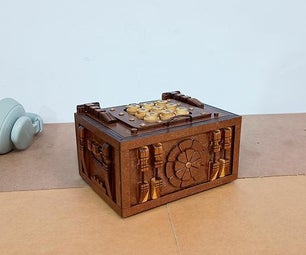
Step 35: Have Fun Jumboinga'ing!


Turn on the battery pack and test that everything still works.
If everything works, start playing! Warning! Do not play around an irritated wife. She will not like the boing boinging and rattling that the game makes. You have been warned!
If your wife or significant other hasn't destroyed the game, go ahead and pretty it up more by adding stickers or labels.
Thank you for reading through this Instructable.

Participated in the
Game Life Contest