

Introduction: Print the IP Address on LCD From Arduino and Ethernet Shield
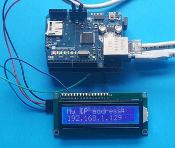


In this Instructable, I will demonstrate how to print the IP address of an Ethernet shield mounted on an Arduino UNO on a 16x2 LCD screen using a serial interface (I2C).
This project was born out of necessity, you do not have to log a laptop with you at work to get the IP address of those pesky wall jacks. Instead, you can build this project, attach a 9 volt battery to the Arduino and that's it.
My colleague wants to replicate this project using a raspberry pi, so here you go Fredo, make your first Instructable, leave comments to encourage him.
I used the sketch in the Arduino library site, https://www.arduino.cc/en/Reference/EthernetIPAddr... and the example DHCPaddressPrinter as a base and I built on them. Both examples print the address on the serial monitor, but with a little tweaking, I was able to output the information on the LCD.
Step 1: Parts You Need for This Project


For this project, you will need:
- An Arduino UNO or Mega
- An Ethernet Shield
- A 16x2 LCD with I2C
- A USB type A to B cable
- 4 jumper wires male to female
I like to color code the jumper wires for easier identification. Black for ground, red for +5 volts, blue for SCL and green for SDA.
Step 2: How to Connect the Electronic Parts


The first thing I did was to bend the ends on the green and the blue jumper wires because they will have to be connected on the Arduino SCL and SDA PINs under the Ethernet shield.
Then I connected the male end of the green jumper wire on the SDA PIN on the Arduino
Then I connected the male end of the blue jumper wire on the SCL PIN on the Arduino
Next mount the Ethernet Shield on the Arduino
Then connect the wires:
- The green female end on the SDA pin on the I2C
- The blue female end on the SCL pin on the I2C
- The red wire from the VCC on the I2C to the 5V on the Shield
- The black wire from the GND on the I2C to the GND on the Shield
Step 3: The Sketch


We start the code by adding the libraries:
#include Wire.h // LCD #include LCD.h // LCD #include LiquidCrystal_I2C.h // LCD #include SPI.h // Ethernet #include Ethernet.h // Ethernet
You can download the libraries from GitHub:
LiquidCrystal: https://github.com/fdebrabander/Arduino-LiquidCrys...
Ethernet: https://github.com/arduino/Arduino/tree/master/lib...
The lines below are used to define the MAC address of the Ethernet shield, define a variable called ip and set it as the fallback address in case the DHCP did not respond, then initialize the Ethernet client.
<br>byte mac[] = {0x00, 0xAA, 0xBB, 0xCC, 0xDE, 0x02}; // MAC Address of the Ethernet Shield IPAddress ip(127,0,0,1);         //Fall back IP address
EthernetClient client;         // Ethernet initialization (port 80 is default for HTTP)
Then define the PINs on the I2C so we can communicate with the LCD and we initialize the LCD:
#define I2C_ADDR          0x27      //Define I2C Address where the PCF8574A is
#define BACKLIGHT_PIN      3
#define En_pin             2                                                             #define Rw_pin             1
#define Rs_pin             0
#define D4_pin             4
#define D5_pin             5
#define D6_pin             6
#define D7_pin             7
LiquidCrystal_I2C      lcd(I2C_ADDR, En_pin,Rw_pin,Rs_pin,D4_pin,D5_pin,D6_pin,D7_pin);  //Initialise the LCD
The void set up is straight forward, we start the serial monitor at 9600 bauds, tell the Arduino that we are using a 16x2 LCD and turn on the backlights on the LCD.
void setup()<br> {
    Serial.begin(9600);  //begin serial

    //Define the LCD as 16 column by 2 rows
    lcd.begin (16,2);

    //Switch on the backlight
    lcd.setBacklightPin(BACKLIGHT_PIN,POSITIVE);
    lcd.setBacklight(HIGH);
  }
The void loop:
I opted to use the Ethernet.maintain() in the void loop because I want the shield to constantly look for an IP address otherwise I will have to reset the board between wall jacks.
The if statement reads as follows: if the DHCP does not respond "Ethernet.begin(mac) ==0" then assign the fall back address defined above "Ethernet.begin(mac, ip)" otherwise execute the printIPAddress() routine.
void loop()<br>  {
    Ethernet.maintain();               // Keep looking for an IP address
    if (Ethernet.begin(mac) == 0)      // start the Ethernet connection, connect to DHCP.  {
      Ethernet.begin(mac, ip);         //if it fails to get an IP from DHCP, use the fall back value
    }
    printIPAddress();                  // print your local IP address:
  }
The printIPAddress:
In this part, the first thing we do is to clear everything on the LCD scree using the lcd.clear() command, then I set the cursor on the first column of the first row using the lcd.setCursor(0,0) command and display My IP address: on the first line of the LCD and on the serial monitor. Then move the cursor to the first column of the second row on the LCD and print the IP address using the command lcd.print(Ethernet,localIP()) on the LCD and Serial.println(Ethernet.localIP()) on the serial monitor.
void printIPAddress()<br> {
lcd.clear(); //Clear the LCD
lcd.setCursor(0,0); // Set the cursor on the LCD to Col 1 Row 1
lcd.print("My IP address: "); // Print on text on the LCD
Serial.print("My IP address is: "); // Print text on the serial monitor
lcd.setCursor(0,1); //set the cursor on the LCD to Col 0 Row 2
Serial.println(Ethernet.localIP()); // Print the IP address on the Serial monitor
lcd.print(Ethernet.localIP()); // Print the IP address on the LCD
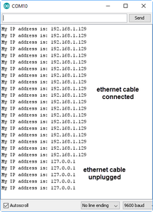
}After connecting the Arduino to the computer and uploading the sketch, you should get the results you see in the pictures. If the network jack is active, the IP address will display on the LAC and on the serial monitor ( I use the serial monitor only for debugging) and if it is not active, the LCD will display 127.0.0.1.
You can eliminate the fall back IP by removing the line:
IPAddress ip(127,0,0,1); //Fall back IP address
and the LCD will display 0.0.0.0 instead.
Concern:
The only issue I have with his code is if the jack is not active, it will take the 60 seconds for the lin (Ethernet.begin(mac) == 0 to return a zero value. I tried editing the file DHCP.h file in the library to reduce the time to 10 seconds but it did not work. If anyone knows how to reduce the time please feel free to comment.
the line I edited is :
int beginWithDHCP(uint8_t *, unsigned long timeout = 60000, unsigned long responseTimeout = 4000);
int checkLease();
I tried changing 60000 to 10000.
Thank you and keep making.

