

Introduction: Remote Access Your Home Alarm


I made this project to give me remote access to my Home Alarm Panel - as I wanted to know if the alarm had gone off on my home while I was away. I also wanted the ability to read the logs - and reset the alarm if I decided it was a false alarm.
It is a generic system - that should suit any alarm system. I have tried it on several alarm panels. It is modular, you can choose what to enable - and only two Alarm Panels that I have tried will support all the features that this project has to offer.
It features:
- Monitors for Alarm activation
- Emails you when the alarm goes off
- Built in HTML Server and Web Pages
- No moving parts - no fans, or drives - Just Two or three Components.
- Easy to Assemble
- Allows you to Set and Unset the system
- Password protected
- Allows you to browse and monitor the home via Mobile
- Has Mobile phone and Desktop display modes
- Cost to build is under $20
Plus the software is all provided for you to expand to possibly remote control other devices - heating, lighting, flood monitoring etc.
Step 1: The Components


The project is modular - make what you need and what your alarm can support.
You will likely need tweak some things to suit your brand of alarm.
There are three main components to this project
Remote Status View
When you browse to the device - there are Green Leds that show all is ok - they can be configured to change Red if there is a problem. Hooking these to the alarm ouputs of the Alarm Panel will let you see the Arm Status of the alarm remotely. Note: you must use a mechanical relay or opto isolator (circuit on next step) or something similar between the Alarm Panel and the Arduino as the Alarm outputs can be 12v-14v and the Arduino can only accept 5v max.
Remote Notification via Email
The system can email you when an alarm goes off. See the comments in the code for where to specify the Email address.
Alarm Log Monitoring
This allows you to see when the alarm was set/unset. What alarm has activated and any other warning like power fails or tampering etc. To do this you need an alarm that can out put the events to a serial device - the Alarms I have got this to work on are an Aritech CD91 and an Aritech CD34 which have the option to connect up an old style dotmatrix printer to the alarm. Instead of a printer - you hook up the Arduino - and it will monitor this information and record it to its flash memory. When you browse to the device, the past events will be visible to view. Memory is very limited on the Arduino so only the past 20 events are stored. Use an Arduino Mega to get four times the storage.
Step 2: The Build


The build is fairly straightforward. I had to solder wires to the DC-DC power supply and as I was monitoring the printer output, I had to solder a chip to invert the signal - more on that below.
Hardware
I used an Arduino UNO with an Ethernet shield.
These are available from many places - shop around the prices vary greatly. Amazon is a good source.
You can either buy the Genuine version, or as the manufactures are open source and allow third parties to make their own versions - these clones will work also and you can get both for under $10 each.
For the power - you need 5V - I used a DC to DC converter from Ebay - these are really cheap (Aprox $3 to $4) and provide a stable 5V from the Alarm Panels 12V External output supply - without getting hot. Very efficient.
Do not try power the Arduino from the Alarm Panels 5V supply. I prefer not to use the built in 9V DC input of the Arduino as the onboard 9v to 5v stepdown regulator is very inefficient and makes the Arduino get really hot - especially when using the Ethernet shield.
If your alarm supports it and you are building the Printer Monitor (to capture the Event Log) you will need some way of converting the alarm panels RS232 voltage level to the Arduino RX/TX TTL level or 5V.
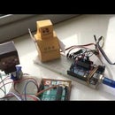
My Alarm Panel (Aritech) - the voltage was correct (0..5V) but was Inverted to what the Arduino expected - It wasn't reliable enough to do in software, so I used a Hex Inverter chip (see photo) to invert the TX from the panel. I used a chip that had 8 inverters only because that's what I had in my spare part bin. Consult the pinout for the chip you use. You will need supply the chip with +5 and GND as well as the signal input from the panel and output from the chip to the Arduino RX pin.
The Photo shows the Hex Inverter chip and Also the DC-DC (12v to 5v) power supply.
Step 3: The Software


I placed all the software on GitHub. Please use the Download button rather than copy pasting from the website to be sure you are getting the code as its intended to be.
The Code is too long to list here - so this is the link to it - "fork" it so you will get notifications it I update it: https://github.com/OzmoOzmo/CastleInternetDialler...
Use the Standard Arduino IDE to program the Arduino (download from from Arduino.cc).
Customizing
This is the fun part - the code and hardware work perfectly for me - it is up to you to configure they system to operate with your Alarm Panel.
The Buttons on the HTML page control the Arduino Digital Pins (see the code for the pinouts). All the Alarms I have seen allow you to designate a zone input as a "Key switch".
This is normally something you can wire to a device - like a physical key you need insert and turn to arm and disarm the alarm - We can use this input to control Arming and Disarming from the Aruino. I have included the circuit for this in the photos above.
On my panels - there is an Output - a High (12V) means the Alarm is Set, a Low (0v) means the Alarm is disarmed. These are fed into the Arduino (using a relay).
The HTML pages delivered will show the status of this input. You could also connect to any LED the system might have to indicate the Alarm is set. Conclusion With some tweaking - this should allow you to monitor and arm/disarm any alarm panel - from any remote web enabled device - such as a mobile phone.
I have created other versions of this project - with much more features but are not as generic as this project but tailor made for particular brands of Alarms. So see my other Instructables if you happen to have an Aritech or HKC Secure Watch alarm...
Feedback welcome :)

Participated in the
Digital Life 101 Challenge

Participated in the
Full Spectrum Laser Contest 2016


