

Introduction: Resistors


Resistors are ubiquitous in electronics and arguably the first "real" electronic component we will be dealing with. They are the little pill-shaped stripe-y things found on most circuit boards. These parts in and of themselves don't do anything remarkably complex, but are vital in purpose. Over the course of this lesson we will learn what resistors are, how to 'read' them, special ways they can be used, and all about a special type of resistor called a potentiometer.
Step 1: Lesson Materials
In this lesson I will be demonstrating how resistors work by making a paper resistor.
While it is optional, if you want to follow along at home and make a paper resistor you will need:
(x1) pencil (preferably 6B, but a #2 will work)
(x1) Paperclips
(x1) 6" x 9" envelope (or piece of paper)
Step 2: All About Resistors

A resistor is an electronic component that limits the flow of electrons. In doing so, it dissipates energy in the form of heat. Put into plain English, electricity has to struggle to flow through something with a high resistance. In doing so, it works up a lot of energy and converts this into heat. It's a little bit like how your body heats up when you do vigorous exercise.

You can think of a resistor kind of like a fixed workout routine for electricity. It provides a known amount of resistance to a circuit, and the electricity always has to do the same amount of work to get through it.

The amount of resistance that a resistor offers is measured in Ohms. The symbol for ohms is the Omega symbol from the Greek Alphabet.
In terms of electronics, the resistor reduces electrical current by a precise amount. If you consider that in a circuit you typically have a fixed input voltage, and resistors offer a fixed amount of resistance, you can then use Ohm's Law to determine how much a resistor will limit current. This is useful in a number of scenarios, including working with LEDs, which will be covered in the diodes lesson.

To measure ohms with a multimeter, turn the dial to the Ω symbol and selecting the proper range (unless you splurged on an auto-ranging multimeter). To determine the correct range, you will need to be able to 'read' the resistor, which we are going to get to in a moment.
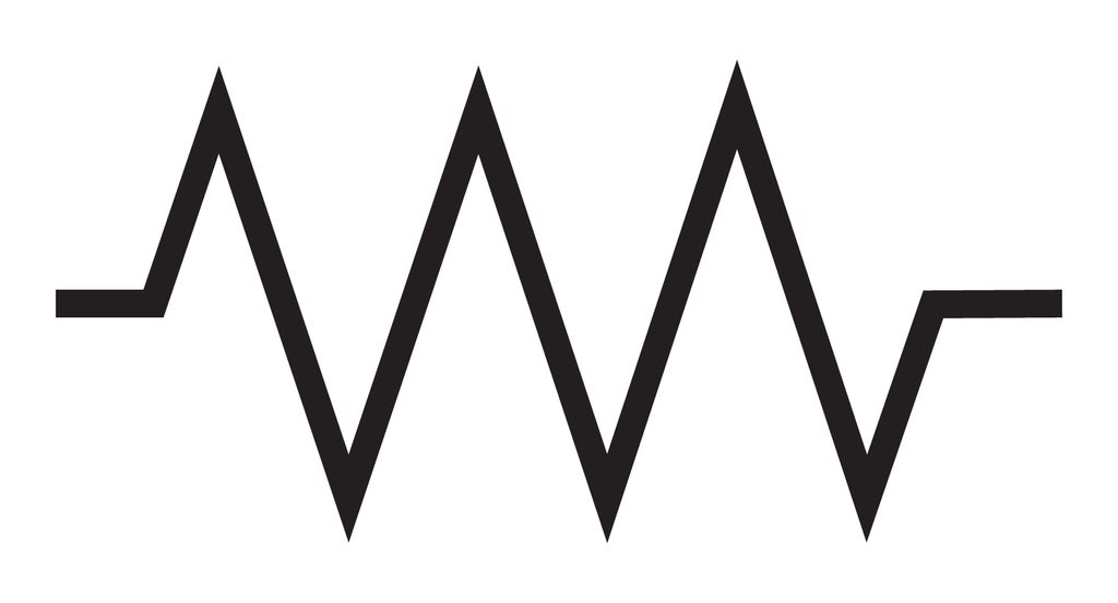
In a circuit, a resistor's symbol looks like a zigzag line. It typically has its value written next to it.
Step 3: Make a Resistor

To better understand how resistors work, let us make our own resistor.

All we will need is a pencil (a #2 will do fine, but a 6B is better), a sheet of paper, and some paperclips.


Take a 6" x 9" envelope and turn it sideways, and then rub a pencil back and forth along the edge. Create a one inch wide band of graphite along this edge. Once you are think you are done, keep going. The more graphite you can put down onto the paper, the better your resistor will work.

Attach paperclips to the probes of your multimeter using jump cables.

Attach one of these paperclips to one corner of the strip.

When you touch the other paperclip anywhere on the strip, you will notice that you get a resistance reading. Congratulations, you have made a resistor.

Now, attach the second paperclip to the opposite corner.

My resistor gives a reading of about 500,000 ohms. I arrived at this because the multimeter is reading in the 2000K (hundred thousandths) range. Thus, it is giving a reading of 500K ohm. Your resistor should roughly be in this range. If your resistor reads much greater than this, add more graphite to increase its conductivity.
All resistors operate along the same principle. The paper resistor I have created offers the same resistance to a circuit as a standard carbon film resistor capsule.
Step 4: Reading Resistors

We can determine what sort of resistor we have by looking at the packaging.
Telling its current rating can typically be established by the size of the resistor. This is something you will figure out intuitively in time, and not remarkably important for the kind of low-current circuits you will be working with when getting started.
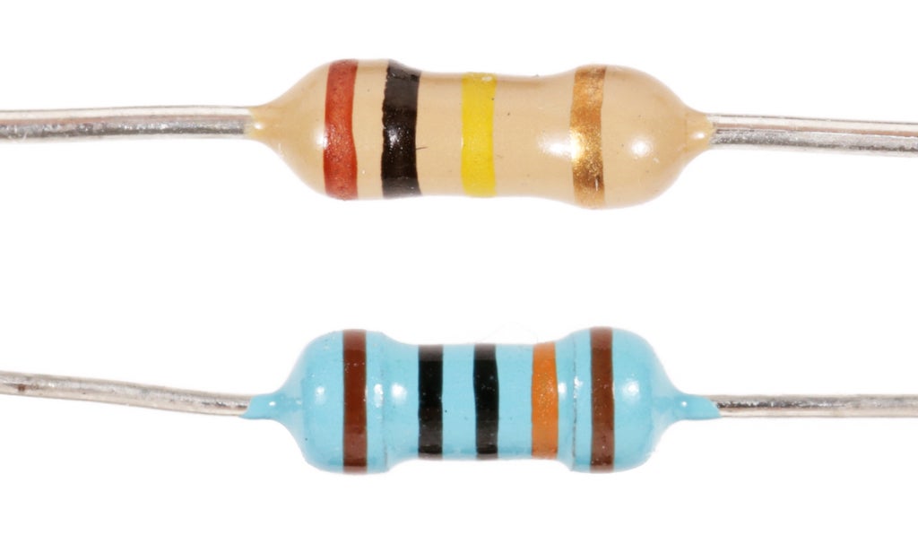
Determining how much resistance a resistor offers is a little trickier and can be established by deciphering the colored stripes from left to right towards the tolerance marking. You will typically see four stripes, but you may also encounter resistors with five.
Resistors with four stripes are the most common. These will likely be the type you are working with most.
When reading a resistor with four stripes, the first two stripes are combined together to form a number between 1 and 99. The third marking is the multiplier. The last marking determines the tolerance, which will be discussed further in a moment.

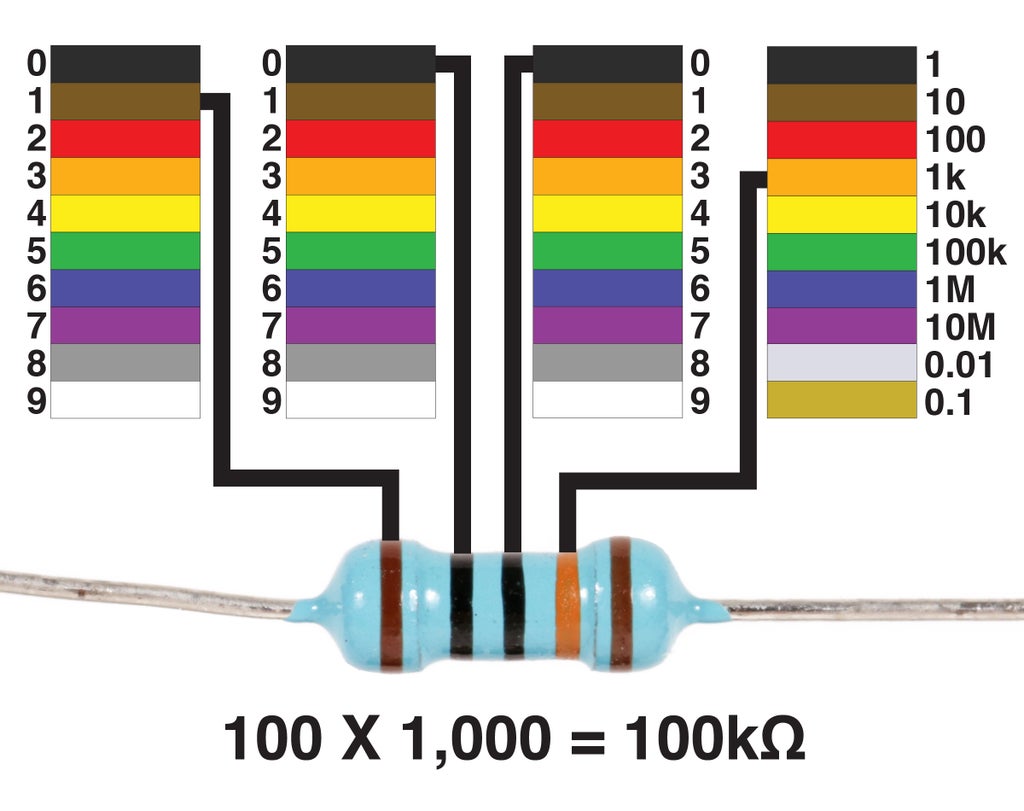
For instance, in the following example, the first two lines represent 1 and 0, which is combined together as the number 10. This is then multiplied by 10,000 (which is the multiplier). The result is 100,000Ω.
However, when a resistor is 1,000 or more ohms, we measure it in kilo-ohms. A kilo-ohm is basically equal to 1,000 ohms. So, 100,000Ω is shortened to 100kΩ. Basically, it is 1,000 ohms times 100. All we are essentially doing is removing three zeros from the number, and replacing them with with k.
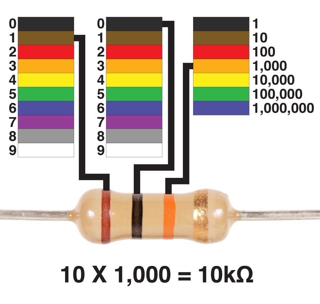
If that was confusing, let us look at another example. This resistor has the same initial number of 10, but a multiplier of 1,000. When multiplied together, these numbers yield a resistance of 10,000Ω or 10KΩ.

Now, let's say the first two numbers were to change, and the multiplier were to decrease. In this example, the first two colors when combined create the number 68. When multiplied by 10, we get the number 680. Since 680Ω is less than 1,000, we just call this resistor 680Ω.
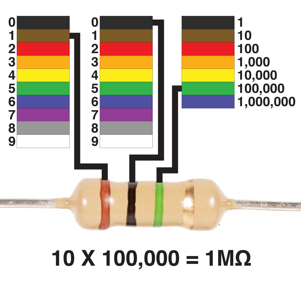
One last thing, if there is a million or more ohms, we then measure in mega-ohms. For example, this resistor is worth 1,000,000Ω. This is shortened to 1MΩ.
Resistors with 5 stripes are a little less common, but just as easy to read. Let us briefly consider how to read them. Like the 4 band resistor, you first find the tolerance marking on the far edge, and then read left to right towards the marking.
However, where they differ is in that the first three stripes get read as a single number, and the fourth stripe is the multiplier. So, in this case, we can determine the first number is 100 and it gets multiplied by 1,000, giving us a resistance of 100K.
The fifth stripe is the tolerance marking.
Step 5: Tolerances

Just like you and I, resistors are not perfect. However, they strive to be as good and as consistent as they can. This is where the tolerance band on the resistor comes in.


A resistor with a gold band has a resistance with a +/- 5% tolerance or - you could say - margin of error. What this means is that the resistance can be over or under its value by 5%. So, if you had a 100K resistor and measured with a multimeter, it could read anywhere from 95K to 105K.
For all of the circuits we will be building here, such approximate values will do fine. We often think of electronics as an exact science, but the truth is that there is a bit of wiggle room in most of what we make. As you begin to dive deeper into electronics you will realize that there is enough fluctuation in circuit building to allow for experimentation and creativity. While this might be a lot to process right now, bury this idea in the back of your head for later.
Anyhow...

Four band resistors have a typical tolerance of +/- 5% and this is indicated by a gold band on the far right.

Five band resistors have a typical tolerance of +/- 1% and this is indicated by a brown band on the far right.
Step 6: Variable Resistors

A variable resistor is a resistor whose value varies within a set range.

Some of the most common types of variable resistors you may encounter include photocells which change in relation to light, bend sensors which change in relation to being flexed, and FSR (force sensing resistors) that change resistance when you apply pressure upon their surface. You also might encounter a host of other variable resistors that change in relation to heat, moisture, and gas, to name a few.

Most importantly, there is the potentiometer. This is the most common variable resistor and utterly ubiquitous in your day-to-day life. Every time you use a slider or knob on an electrical device, you are using a potentiometer. For instance, every single mechanical light dimmer you have ever used is a potentiometer.

Potentiometers come in a wide range of resistances, and have a physical actuator that sweeps from 0 ohms resistance to whatever value is marked upon it.

The inside of a potentiometer does not look remarkably different from our paper resistor. In fact, it is basically just a miniaturized version of what we have made. Instead of moving a paperclip, there is an actuator knob or sliding lever that moves a conductive element over an electrically resistive surface.

By connecting a wire to either one of its outer terminals, and another to the center terminal, we can wire a potentiometer as a variable resistor.

In a schematic a variable resistor looks like a normal resistor with a line reaching around and pointing back at itself.
You may also be wondering why the potentiometer has three legs, when two seems to be enough to work as a variable resistor. We will get to that in a moment, but first, I need to introduce an important concept.
Step 7: Voltage Dividers

Let's mirror a potentiometer for a moment and add a third paper clip close to the center of our paper resistor. Now, if we were to connect voltage across the outer terminals and use a multimeter to measure from either of the outer terminals to the center terminal, you may notice something interesting. The voltage reading we are getting is about half of the supply voltage. By "dividing" the resistor in two, we have created a voltage divider.

Resistors can be placed in series to make voltage dividers. These voltage values are in proportion to the values of each resistor. The resistance value of the two resistors is less important in determining the voltage than the ratio of values between the resistors.
If you run the simulation, you will notice that two 10K resistors in series between 5V and ground will have the same voltage rating at their midpoint as two 100K resistors between 5V and ground. This is because there is an equal ratio between both sets of resistors.
On the other hand, if we were to change the resistors of these voltage dividers to have uneven values, the voltage will increase or decrease.
By changing the 100K resistor connected to power to 47K, the voltage reading increases. This is because there is less resistance between the positive terminal and the midpoint than from the midpoint to ground, so voltage can flow more easily from power. On the other hand, we have decreased the value of the 10K resistor connected to ground to a value of 4.7K. In this scenario the voltage decreases because electricity can flow to ground more freely than power.
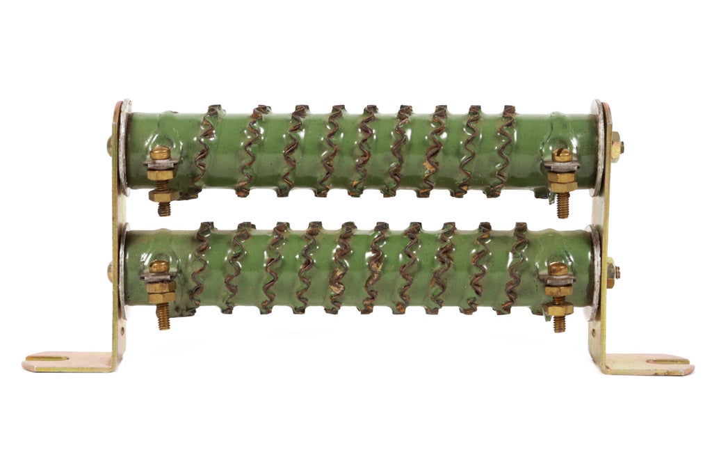
These two gnarly looking metal tubes are actually giant resistors used as voltage dividers for converting the electrical system in a military jeep from 24V to 12V. While crudely effective, it is by no means the best way to do this. Resistors work by converting energy to heat, which is a wildly inefficient way to solve the problem of voltage conversion. Additionally, unlike the massive resistors pictured above, standard resistors are not rated to handle the current that a typical circuit requires. Trying to power electronics through a voltage divider will in all likelihood release the 'magic smoke' from one component or another.
Step 8: Potentiometers

When we connect the end of the resistor to power and ground (respectively) and move the probe along the paper resistor, you may notice that the voltage changes.
If it wasn't clear by now, let me reiterate what is happening. The paper resistor is functioning as a giant variable voltage divider.
It should now be apparent what the third connection in the potentiometer is used for.

As the potentiometer's knob is turned, the wire connected to the center pin is swept along, creating two discrete resistance values between power and ground. This pins is basically functioning like the middle paperclip in the paper potentiometer example. It allows us to change the voltage as it is turned one or another.
In the following wiring configuration the voltage will increase when the potentiometer is turned clockwise, and decreased when turned the other way.
It does not matter what the resistance of the potentiometer is, when wired in this manner, the center pin on all potentiometers will be adjustable between 0 volts and the supply voltage.

In a schematic, a potentiometer looks like a resistor with an arrow pointing towards the center.
Step 9: Tapers
While the sweep in the potentiometer varies the voltage, not all sweeps are the same. There are two types of sweeps you will encounter, and they are typically referred to as a potentiometer's taper.

A linear taper has a linear response curve. What this means is that when you sweep the potentiometers actuator through it's full range, the resistance will increase or decrease steadily.
This type of potentiometer is most common and used in most things.

On the other hand, a logarithmic (or "log") taper has a response curve which looks like a logarithmic curve (or in layman's terms - this dude's smirk --> ¯\_(ツ)_/¯ ).
The reason you would want this type of potentiometer is largely for adjusting audio volume. Loudness is not linear, but logarithmic. If you were to use a linear potentiometer for adjusting volume, it would go from being really quiet to really loud very suddenly. By using a logarithmic potentiometer, you can follow the curve of the music and have a more gradual increase in volume.
Thus, stereo volume knobs tend to be logarithmic. Although these potentiometers are not prevalent, they are common enough that you will encounter them. In fact, we will be using them when we build our audio mixer.


