

Introduction: Rose Window Themed Night Light, Part Deux


“The greatest products of architecture are less the works of individuals than of society; rather the offspring of a nation's effort, than the inspired flash of a man of genius...”
Victor Hugo, The Hunchback of Notre-Dame.
The architecture of any building, to me, is very seldom the sole idea of one person. The architect would be influenced by his or her training. He or she would need to draw inspiration from the surrounding. The considerations of his or her design would also be geared towards addressing a set of problems specific to that period in time and possibly be constrained or aided by the available building technology. Thus in some sense, a building always summarizes the prevailing trend of that epoch. The above quote from Victor Hugo in 'The Hunchback of Notre-Dame' perfectly summarizes this idea.
Of course, Notre Dame refers to none other than the Cathédrale Notre Dame de Paris one of the main Cathedral in Paris located on the Île de la Cité, an island in the middle of the Seine river. My appreciation of old architectures stemmed mainly from the influence of a good friend of mine. For the back story refer to Rose Window Themed Night Light. Notre Dame de Paris is one of the major cathedrals in Paris, of which there are many excellent examples of, that I visited during my first trip to Europe. When I first crossed one of the numerous bridges to Île de la Cité, even before I caught a glimpse of the whole profile of the cathedral, my imagination was immediately captured of the south rose window. The scene has remained in my mind ever since.
Previously, I made a night light based on the Chartres Cathedral's north rose window which I documented in Rose Window Themed Night Light. I am thinking of making it part of a, trilogy?. The build here would be the center piece of the three. So here goes...
Step 1: Parts Needed
1. 3 mm thick plywood or MDF (enough to cut out 2 pieces measuring 342.83mm x 342.83mm).
2. 6 mm thick plywood or MDF (enough to cut out 4 piece measuring 342.86mm x 122.29mm and 1 piece measuring 342.83mm x 342.83mm).
3. Colored acrylic sheet (translucent blue in my case, larger than 320.07mm x 320.07mm)
4. 12V white LED lighting strip (about 1m in length).
5. Wood glue.
6. Double sided tape.
Step 2: Designing


Drawing this rose window in Solidworks was a lot harder than in Rose Window Themed Night Light. I did not manage to find any reference on what symmetries to use to come up with the design. I started by measuring the proportion of the key features of the rose windows in photos and drawing them out. It was only until much later that I found this link:
QUADRALECTIC ARCHITECTURE – A Panoramic Review by Marten Kuilman
specifically this page,
https://quadralectics.files.wordpress.com/2013/09/270.jpg
It sort of addresses the issues of how to draw some of the common features found in rose windows. Initially I planned to make the rose window out of three layers. But upon further study of photos of the rose window, it seems that two layers would be sufficient.
I started with the outer layer of the rose window. First I drew all the lines corresponding to the features of the first layer of the rose window. I then use 'Offset Entities' to offset 1mm in either direction of those lines. Then I went in and meticulously deleted all the unwanted lines using the 'Trim Entities', merging all the structures. Symmetry is your greatest allie when it comes to drawing rose windows. Essentially one could draw a quarter of the window and mirroring it over the four quadrant would take care of the rest.
As with the previous project, there were significant issues when it came to trying to extrude the sketch in Solidworks. There were a lot of very short line segments and open contours left over from the trimming process. This was why I only worked to clean up a quarter of the rose window. When this was done I used the 'Mirror Entities' to get the whole rose window. A deal of time was spent sorting this out. After the outer layer was finished, it was used as a template to draw the inner layer.
From previous builds, I knew that the particular laser cutter I was going to use always over-cut a square hole by 0.2mm both ways. Thus some of the slots at the edges were drawn slightly smaller than their corresponding tabs. This was to ensure a tight fit for gluing.
After all the parts were drawn, I then test assembled them in Solidworks to make sure I did not make any silliy mistakes. The good old 'measure twice, cut once' quote comes to mind here.
Step 3: Fabrication


For this build, I did not source for the materials from the local arts and craft store. The 3mm and 6mm thick plywood sheets available there are just a tab too small for this project. So I made used of the materials available at the laser cutter's instead and they have huge slabs of plywood on tap. As a time saving measure, I assembled all the parts of the same thickness, flat and side by side in Solidworks. I then converted these assemblies into Solidworks part files and chose a face-on view to save them as .dxf files for the laser cutting. I have included the .dxf files for the individual parts with their thickness indicated in the file names. There should not be any issue in combining these cutting templates for materials of the same thickness using any vector graphics editing program.
I started laser cutting the two pieces that made up the front face. Since these were the two pieces that had the intricate patterns, I figured if anything were to go wrong it would most likely happen while cutting these two pieces. Lo and behold soon after starting, something did go wrong with the cutting. There was a jet of air from a nozzle next to the laser head. It was there to prevent the soot from contaminating the output optics. But in this case the air jet was so strong that it broke off one of the spokes of the pattern while cutting the adjacent hole.
Having beaten Murphy's law, sort of, we restarted with a reduced air flow in the jet and used MDF (it is stronger than plywood) instead. As the laser cutting continues, there were a few heart stopping moments when we were not sure whether the laser cutter was capable of cutting such intricate structures. It is therefore probably prudent to add a warning here. So here goes:
***Warning***
The laser cutting template contains intricate patterns. Depending on the specification and tolerances of the laser cutter in use, it may or may not be able to effect the cut. So experimentation is the key here I guess.
There were also significant darkening on the spokes of the pattern due to the soot from the cutting. This was probably due the close proximity of the two adjacent cut lines. Anyway, once I gotten all the MDF parts, nothing a little sanding (not sure how wise is it to sand MDF) would not remove. After checking, the two front faces did not match up perfectly (fortunately it was not a show stopper). i think this was because there was a slight initial warp in the 3mm MDF.

Step 4: Assembly


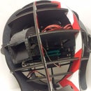
For this build there were not much assembly required (an exploded view of the assembly is shown in the designing section). In total there were three big wooden panels (two front faces and one back face), four small wooden panels (two for the sides and two for the top and bottom) and finally one square-shaped acrylic sheet. I opted for a slightly different assembly sequence from Rose-Window-Themed-Night-Light.
I applied a semi-generous amount of wood glue on the tabs for the side pieces. Using the back piece as a jig (I left the back piece unglued so that I can still access the inside in the future), I assembled the four side pieces. I then wiped away the excess wood glue that had been squished out.
Next I glued on the front inner face followed by the front outer face, taking care not to apply too much wood glue here (the excess glue was excruciatingly hard to clean off if it squished in between the intricate patterns).
Next the blue translucent acrylic sheet was attached using double sided tape behind the front face. This time round I am going for a constant glow, so for the lighting I taped on a LED lighting strip inside the box. To power it, I used a 12V adaptor which I also secure using double-sided tape in the box. After drilling a small hole at the back panel for the wire (I did not pre-cut this hole in the fabrication phase as I was still unsure about the choice of lighting) and closing the box off, Voila! The build was completed.

Participated in the
3D Design Contest

Participated in the
Wood Contest

Participated in the
Make it Glow!


