

Introduction: Rotary - Encoder Control With Ti Launchpad


There are many cases where one needs a button, encoder, or a device to use it as a input for several settings.
The rotary encoder having no physical connection to a circuitry is a very sophisticated and long term solution due to many reasons.
Reasons:
- no wearing of the parts
- no physical or electrical contact with the circuitry
- silent, without noisy sounds
- easy replaceable
Step 1: Understanding the Setup and the Main Task

Since couple of months I'm working with Ti microcontrollers. Mostly with the Launchpad Ecosystem and Energia IDE. I wanted to connect display to Piccolo LaunchXL Launchpad, in order to test couple of programs I have written. One of the main tasks was to control a Rotary-encoder with magnetic construction and use it as a input for volume, or other settings. First of all check the suitable controller/launchpad topology and datasheet to spot the suitable pins which can read the input (analog or digital etc..), in our case the rotary part is connected with shaft to a wheel which has predefined drilled holes on other side (Black part). The Silver metallic side corresponds to the part which user can touch to rotate. The holes are meant for 2x optocouplers, TCST-1103, from Vishay. Those 2 optocouplers are installed together for 2 digital- inputs. Basically in my setup I have two digital inputs from optocouplers which must be read by MCU. Those optopcouplers have defined laser aperture size and parameters, so when the wheel rolls the beam is being interrupted and that can be read by the suitable digital pins.
Step 2: Texas Instruments Launchpad, LaunchXL F28027 Piccolo MCU
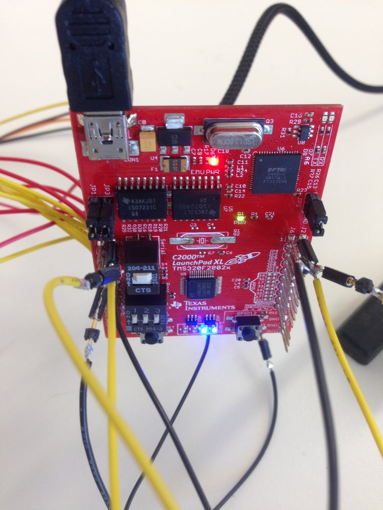
The Piccolo MCU's from Texas instruments are performance controllers for wide variety of applications, and have up to 40 pins, with high definition ADC and other working properties. I don't want to discuss the Launchpad here, just small intro about the controller is enough.
Basically one can use any other controller, my choice is related to other parameters of the controller. The wiring is as follows from the optocouplers, 2 - signals, then, Vcc and GND respectively. Please refer to optocoupler connection instructions, because they need to be connected with certain resistors. The pins marked with green lines are both digital and analog. In my setup I have started with AA6 and corresponding pins. In case of Launchpad use, dont forget to put the S4 switch and the S1 in up position, means all switches are in UP.
Step 3: LCD Display for Viewing the Data

after everything is completed successfully, I suggest a connection of display, in order to view the data directly on LCD and also one can get familiar how the mcu handles all the stuff with various modules already attached to it. In my case I got a simple 16x2 display with Motorola driver. It does come with several connection interfaces: I2c, and SPI . I used 12 pins to connect the interface. The back-light and the contrast via potti. The nominal supply voltage is 5 volts. Luckily the Launchpad has both 3.3 and 5.0 volt connection rails. I have used just 4 bit data mode, which means that from 8 data pins, only 4 are connected to the launchpad and the other four are connected to the ground.
Step 4: Final Adjustments and Launch

if all connections are done properly and the Launchpad link with pc is active, and there are life sighs from Launchpad onboard leds, one can program them easily and later use to check various stages of code while it is executed. Time to load the code. I have assembled my code in Energia. In case the code is needed, please message me. The CCS studio which is a better and more feature rich code assmebly_/building platform can be use as well. When the program is loaded and the mcu, is powered, the display should start working. In case if the display shows nonsense or just blue screen, please check the data bus. Mostly it happens when the wrong data cable are connected. If there is no power et all, check the connection with the pottentiometer and launchpad. Could be that the power supply chain is faulty.
The Code.
In source code, one should use ISR = interrupt service protocols. It is better, because if your code is long and there are other thing to take care, than the mcu would react to encoder with small lag (ms- 1 sec delay). In my case I used interrupt to monitor the state of the encoder. Then just add the LCD libraries to program the display to show whatever you want. The status of the encoder, or the volume or some info, its up to you. In my case the display is programmed to show the volume, in decibels, the current reading, and some other info.
Basically that's it. Very cool setup and nice to use. I highly recommend as an engineer this setup.
In case of questions, please post a comment or message me.
Have fun while building ^^))

Participated in the
Lights Contest 2017


