

Introduction: Smart IoT Garden


If you are anything like me, you like fresh fruit and vegetables on your plate, but you don't have enough time to maintain a decent garden. This instructable will show you how to build a smart IoT garden (I call it: Green Guard) which waters your plants for you and warns you about dangerous situations such as: too much sunlight, not enough sunlight and out of water.
This is all achieved by using a couple of simple sensors and an actuator controlled by a Raspberry Pi. On the website, you can view the measurements from these sensors and take control of the water flow.
Step 1: Materials & Tools
Materials:
- 1x Raspberry Pi 4
- 1m piano hinge
- 1x battery holder 8x AA
- 8x AA batteries
- *1x solenoid valve 12V 1/2"
- 3m water tube (plastic, nylon...) 12mm
- 1x tailpiece T shape
- 2x tailpiece 1/2" 12mm
- 5x hose clamp
- 1x 5 liter jerrycan
- 4m wooden planks
- 1x wooden panel 100cm / 50cm
- 1x pond foil 2m / 1m
- min. 50 screws
- 1x breadboard
- 2x magnetic closures
- 1x npn transistor
- 1x temperature & humidity sensor
- 1x LDR light sensor
- 1x soil moisture sensor
- 1x LCD Display
- 2x 1/2" piping L shape
This document shows you where I got these materials.
*It's important that the solenoid valve has no minimum operating pressure. If it does, the water will struggle to get through.
Tools:
- miter saw (optional: any other kind of saw)
- hand drill (optional: screwdriver)
- staple gun (optional: screws)
- wood glue
Step 2: Building the Circuit
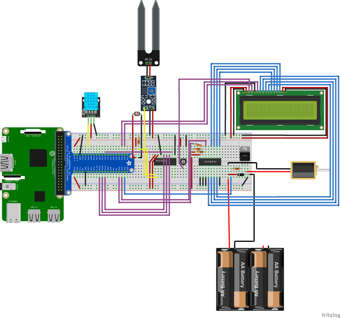
The following components will be connected to the Raspberry Pi:
- MCP3008
- LDR light sensor
- Soil moisture sensor
- DHT11 Humidity & Temperature sensor
- PCF8574
- LCD display
- TIP120 transistor
- solenoid valve
Two of the sensors (LDR and Soil moisture) are connected to an MCP3008 which allows for analog signals to be read by the Raspberry Pi. I'm using the PCF8574 to write data to the LCD because it saves a lot of GPIO pins.
You can just follow the image above when building the circuit.
Step 3: Setting Up the Database


To really have full control over your garden, you'll want to see a timeline showing all the measurements from your sensors. I'm using an SQL database to save all these measurements.
I've prepared a self-contained file which includes the entire database needed for this project. You can find this in the database-export folder in my Git repository and import this database in MySQL Workbench by opening server > data import and then selecting the self-contained file and creating a new database.
This database contains four tables: tblmeasurement, tbldevice, tblwarning and tblaction. Tbldevice contains all the sensors and the actuator. The messages in tblwarning are in Dutch, but you can easily change them by clicking the execute symbol on the table, changing the messages and applying the changes. Tblaction contains actions which can be executed by the program I'll talk about in the next step. These actions are e.g.: measuring temperature, automatic activation solenoid valve...
Step 4: Programming


You can find all the code necessary in my Git repository. Front end and back end.
This program does all the technical stuff such as: read sensor data, activate the actuator...
Above, you can see some pictures of the website. It's in dutch but you
Step 5: Building the Basic Shape of the Garden

The first step of making the physical project is building the basic casing of the garden. Start with sawing some planks in the following dimensions:
- a - 2x 100cm / 20cm
- b - 2x 46.4cm / 20cm
- c - 1x 46.4cm / 18.2cm
- d - 1x 46cm / 18cm
- e - 1x 15cm / 20cm
- f - 1x 31cm / 20cm
First, attatch planks a on both sides of the wooden panel. The best way of attaching this goes in four steps:
- drill holes on the panel where the screws will go through
- use a countersink drill bit to make place for the head of the screw to go in
- put a line of wood glue where the plank will be attached
- place the plank on the glue and drill the screws through the holes you drilled earlier
5 screws will be enough to hold planks a. Then you can do the same with planks b, for which I used 3 screws on the bottom and 2 on the side.
Step 6: Build the Water Reservoir Holder


Attach plank e in the corner you can see in the picture using the method I explained in the previous step. You can easily do this on your own by using a piece of wood and a clam (see second picture).
To support this plank, make a small wooden beam with 45 degree angled sides on the top and bottom. To make sure it touches the floor when attaching it to the upright plank, draw a line where to saw the top side like I do in the third picture.
Next, use some scrap wood to build a frame fit for the jerrycan you use. Attach the frame to the platform using wood glue. The frame I made wasn't totally level so I screwed it tight with two clams while glued and let it set for a night.
Finally, you'll need to attach the L shaped piping to the bottom of the jerrycan and make a hole in the plank supporting the jerrycan so the piping can go through. To attach the piping, I welded a fitting piece of piping to a metal plate which I attached to the jerrycan using Sikaflex universal glue. Alternatively, you can just push a piece of tubing in the hole you make in the jerrycan and put enough universal glue on it so it stays in place. You can make the hole below the jerrycan with a hole saw bit for your hand drill.
Step 7: Connecting the Piping and Tubing


Before connecting any of the tubing, attach the pond foil on the inside of the garden part of the project. I fixed it on the outside of the project with a stapler gun. You can fold corner pieces so they fit nicely and cut away parts where there's too much foil.
With this done, you can start drilling 2 holes from the garden part to the management part at approximately 15 cm high for the tubing to get to the garden itself. You can reduce the amount of splinters and drill through the foil by fixing 2 pieces of wood on the plank and drilling through them as in the picture above. You can push two tubes through the holes and connect them in the middle behind the plank. Then you can drill some 2.5mm holes in the tubes for the water to come out (and don't forget to drill one hole on the upper side of the tube so the water can keep flowing while the solenoid valve is closed).
Drill two holes (not all the way through) at the end of the garden to attach the end of the tubes to. Glue 2 cylindrical pieces of metal on the inside of the holes and push the end of the tubes over them.
Next, attach a piece of wood to the floor panel next to the water reservoir (as in the picture). This is where the solenoid valve will rest on, so test its position to make sure your solenoid fits onto it. On top of this piece, attach an L-shaped piece of metal where the solenoid valve will be fixed onto.
Step 8: Integrating Electronics


Start by shaping two pieces of wood. One for the DHT11 and LDR, and one for the soil moisture sensor. You can see those pieces in the pictures above. Attach them as shown in the pictures.
You can hide the wires of the DHT11 and LDR by stapling a piece of pond foil on top of them and poking them through. Drill a hole where the wires can go through.
Next, to make the hole for the LCD display, drill two holes on the diagonal ends of the space for the LCD and use a hacksaw to saw out a rectangle.
You can place the breadboard, Raspberry Pi and 12V battery pack inside behind the lcd in the corner (and use Velcro to hold them down). Then you use a plastic box, cut out 2 sides and place it over the electronics to shield them from any dripping water. Gluing a small piece of wood on the floor panel next to the plastic box keeps it in place.
Finally, drill a line of holes just below the height of the plastic box so the hot air of the Raspberry Pi can escape.
Step 9: Attaching Hinges


The only thing left to do now is attach the last two planks you sawed at the beginning.
First, saw off the bottom right corner of the plank on the side. This is where the power cable will go through.
Then you can screw the hinges onto the planks as in the pictures above.
Step 10: Closing
If you decide to make this project yourself, let me know in the comments (:
Thanks for reading.

Participated in the
Backyard Contest

![Tim's Mechanical Spider Leg [LU9685-20CU]](https://content.instructables.com/FFB/5R4I/LVKZ6G6R/FFB5R4ILVKZ6G6R.png?auto=webp&crop=1.2%3A1&frame=1&width=306)


