

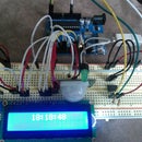
Introduction: Super Simple Arduino Keypad (the Hard Way)


**NOTE - There is a library for Arduino to make using a legitimate keypad so much easier. If you're like me in the least, sometimes you just want to figure it out yourself. There is more to be gained this way, and the learning potential is greater. However, I do not doubt the hard work and dedication that went into the making of the keypad library, which can be found here -
http://playground.arduino.cc/Main/KeypadTutorial
At any rate, let's begin!
Step 1: Inventory Check

For this project we will use the following -
~Hardware~
- Arduino Uno
-Servo Motor (180*)
-Momentary Push Buttons x5
-10k Resistors x5
-LED x2 (Redx1 , Greenx1)
-16x2 Character LCD
-10k Potentiometer
-Assortment of jumper wires
-Breadboard (one large enough for the whole project, or a couple of small ones)
-Don't forget your computer or laptop, and your USB cable for your Arduino
~Software~
-Arduino (of course :3)
~And a good piece of software to get your hands on is Fritzing ( http://www.fritzing.org). Very cool stuff. It has three ways to visualize your circuit - Breadboard, Schematic, and PCB. Plus! You can send in your design and have them make your PCB so you can have a finished product! I haven't tried it yet, but it's an awesome possibility to have at your fingertips! I use Fritzing to make the schematics and a neater, more organized breadboard view :) Best of all, it's a free software.
Step 2: Wiring It Up - Buttons


Make room for the buttons on your Arduino's Analog Pin area A0-A4.
One side of the button will be tied to 5v, and the other side will be tied to ground and one of the Analog Pins. It will work the other way around, too - one side tied to 5v and an Analog Pin, and the other to ground. It's really a matter of preference, depending on if you are looking for a HIGH signal or LOW signal.
I prefer looking for a HIGH signal as I am a worry-wart about a constant 5v being fed into the pin. And I am also an optimist - waiting for something good to happen rather than waiting for something good to disappear :P
Step 3: Wiring It Up - Servo


I have to say, I love me some servo!
Anyways... if you notice, there are three lines coming from the servo - on mine in particular, there is Red, Brown, and Orange. It's obvious that Red is 5v. The brown lead is Ground, and the orange is signal. We will wire it up, connecting the Orange lead to Digital Pin 9 of the Arduino, and the other two leads to 5v and Ground, respectively.
I'm not certain of older versions, but most recent versions of the Arduino IDE come loaded with a servo library and some examples to boot. #Including a servo into your projects is a snap!
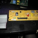
Step 4: Wiring It Up - 16x2 Character LCD


The LCD is a fun little gizmo. Like the servo, there should be a library and examples for using and controlling an LCD screen, as well as tutorials online to help get you going. I'll detail as much as I can here, as the LCD is a tad more complex than the servo.
First, we will wire it up to the Arduino.
The pins on the LCD, from left to right, are as follows -
-1: VSS (Ground)
-2: VDD (+5v)
-3: Contrast (tie this to the 10k potentiometer wiper - middle pin)
-4: Register Select
-5: Read/Write
-6: Enable
-7: Data 0
-8: Data 1
-9: Data 2
-10: Data 3
-11: Data 4
-12: Data 5
-13: Data 6
-14: Data 7
-15: Backlight +5v
-16: Backlight Ground
Connect the power and ground connections to...power and ground, respectively (if your LCD only has 14 pins, chances are it does not have a backlight, therefore, just omit the backlight connections). Pin 3, the contrast voltage, will go to the wiper pin of the 10k potentiometer. You can tie pins 4, 6, 11, 12, 13, and 14 to any unused Digital Pins on the Arduino, as long as it's in sequential order in the code, for example -
LCD Pins Arduino Pins
4 6
6 2
11 5
12 11
13 7
14 3
While that's kind of...odd...to wire it all jumbled like that, it would still work, granted in the Arduino sketch, you have it in that order.
Here's what it would look like -
LiquidCrystal lcd(6, 2, 5, 11, 7, 3)
How the library works, from what I gather, it will designate those Arduino Pins as the LCD pins in sequential order. Pin 6 will be designated Register Select, 2 will be Enable, and so on. Thus, if it's not in order as you wire and code it up, things won't quite work so well.
Wasn't that complicated? Luckily for us, other brilliant individuals wrote the library that does the heavy lifting for us. Kudos to those guys! So all we have to do is tie everything together correctly and it'll be smooth sailin'.
For this particular project, however, will will designate pins 4, 6, 11, 12, 13, and 14 to Digital Pins 2, 3, 4, 5, 6, and 7.
You may be wondering, "But what about the other 4 data pins?". We can get away nicely with just using those 4 pins. Using all 8 pins is supposedly twice as fast, but for what we're doing now, these 4 pins will serve us quite well :)
Oh, and tie pin 5 of the LCD to ground. Tying it to ground will set the LCD to Write - since we are writing to it. Reading from it is not necessary at the moment.
Step 5: Wiring It Up - LEDs


This will most assuredly be a short step. We will use Digital Pins 8 and 10 for the LEDs. 8 for the Green, and 10 for the Red. Just make sure to remember which is which!
Long lead is positive, shorter lead is ground, lest we forget!
Step 6: Coding It Up...now for the Fun!

This will be where it gets a little...challenging...
I did my best not to just follow someone else's tutorial, but instead use what I know. Figure out what works and what doesn't. As usual, you can download my sketch at github (link at bottom), and here I will detail each part of the sketch, piece by piece.
// Here we include our libraries
#include <Servo.h>
#include <LiquidCrystal.h>
// Initialize the libraries and set the pins for the LCD
LiquidCrystal lcd(2,3,4,5,6,7);
Servo myservo;
// const int means Constant Integer. Constants don't change. Fitting since we are using buttons.
//Don't want our Arduino to get confused!
const int button1 = A0;
const int button2 = A1;
const int button3 = A2;
const int button4 = A3;
const int button5 = A4;
// We will be using "countx" to keep track of how many times a button is pressed
int count1 = 0;
int count2 = 0;
int count3 = 0;
int count4 = 0;
int count5 = 0;
// "statex" will keep track of the state of the button. Was it just pressed?
int state1 = 0;
int state2 = 0;
int state3 = 0;
int state4 = 0;
int state5 = 0;
// These keep tabs on the previous state of the button. Was it high? Low?
int prev1 = 0;
int prev2 = 0;
int prev3 = 0;
int prev4 = 0;
int prev5 = 0;
// totalcount is how many times each button was pressed...like a combination.
int totalcount = 0;
// This applies to the LCD. It will be used to display an asterisk when inputting the combination.
int rows = 0;
// And declare the LEDs :)
int red = 8;
int green = 10;
Step 7: Coding It Up - Setup and Loop
// Here we setup how the pins will function (input/output), start the LCD, and designate which
// pin we have the servo attached to. We will also start off with the servo at 0 degrees.
void setup(){
pinMode(button1, INPUT);
pinMode(button2, INPUT);
pinMode(button3, INPUT);
pinMode(button4, INPUT);
pinMode(button5, INPUT);
pinMode(red, OUTPUT);
pinMode(green, OUTPUT);
lcd.begin(16,2);
lcd.setCursor(0,0);
lcd.print(" :ENTER CODE: ");
Serial.begin(9600); // For debug. Visually see the button presses.
myservo.attach(9);
myservo.write(0);
}
// Start off by reading the state of the pins.
void loop(){
state1 = digitalRead(button1);
state2 = digitalRead(button2);
state3 = digitalRead(button3);
state4 = digitalRead(button4);
state5 = digitalRead(button5);
// If the state of the button does not equal it's previous state (1 = HIGH, 0 = LOW), which basically
// means, was it just pressed or released? If the state of the button is HIGH (1)
// we increment the count of that button.
if (state1 != prev1){
delay(10);
if (state1 == HIGH){
count1++;
}
// Note the delay(10). This is important. It facilitates a debounce. Buttons have an intert
// bounciness. You can't feel it, but when you press a button, it sometimes makes
// contact more than once, and the Arduino will see that as multiple presses. The delay
// pauses the program for 10 milliseconds, allowing the button to "settle", and then
// resumes. 10 milliseconds should be long enough, but adjust longer if needed.
else{}
}
// We do that for each button.
if (state2 != prev2){
delay(10);
if (state2 == HIGH){
count2++;
}
else{}
}
if (state3 != prev3){
delay(10);
if (state3 == HIGH){
count3++;
}
else{}
}
if (state4 != prev4){
delay(10);
if (state4 == HIGH){
count4++;
}
else{}
}
if (state5 != prev5){
delay(10);
if (state5 == HIGH){
count5++;
}
else{}
}
// This will help keep track of what kind of actions are going on with
// the buttons. When the button is pushed, its state does not match
// it's previous state, indicating a change. Here we set the previous
// state to the current state, so that the moment you push or
// release, the Arduino knows it, and acts accordingly.
prev1 = state1;
prev2 = state2;
prev3 = state3;
prev4 = state4;
prev5 = state5;
// Then we tally up how many times each button was pressed.
totalcount = count1 + count2 + count3 + count4 + count5;
// This is where we write an asterisk ("*") to the LCD each time a button is pressed.
for (rows = 0; rows < totalcount; rows+1){
lcd.setCursor(rows,1);
lcd.print("*");
rows++;
}
// "rows" is where the cursor is (left to right) on the LCD.
//For each time a button is pressed, we increment "rows" by one, and
// set that as the cursor location. We do this up to a certain point (5)
//because that is how many digits are in our combination.
// Now, if our totalcount reaches 5, we will start looking at how many times
// each button was pressed. If it matches what our predetermined combo...
if (totalcount == 5){
if (count1 == 2 && count2 == 0 && count3 == 1 && count4 == 2 && count5 == 0){
lcd.clear();
lcd.print(" CODE ACCEPTED "); // Code Accepted!
myservo.write(90); // the servo moves to 90 degrees, as if unlocking a door.
digitalWrite(green, HIGH); // green equals good, thus the green LED is on
// make sure the red LED stays off if you didn't get the code right the first time
digitalWrite(red, LOW);
count1 = 0; // Reset all our conunters to 0, starting the process over again.
count2 = 0;
count3 = 0;
count4 = 0;
count5 = 0;
totalcount = 0;
delay(10000);
lcd.clear();
lcd.setCursor(0,0);
lcd.print(" :ENTER CODE: "); // And we're back at the beginning.
myservo.write(0);
digitalWrite(green, LOW);
}
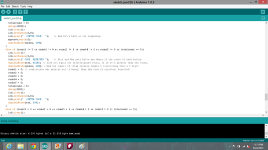
else if (count1 != 2 && count2 != 0 && count3 != 1 && count4 != 2 && count5 != 0 && totalcount == 5){
lcd.clear();
lcd.setCursor(0,0);
lcd.print(" CODE REJECTED "); // This and the part below are where if the count of each button
digitalWrite(red, HIGH); // does not equal the predetermined count, or if it's greater than the count,
digitalWrite(green, LOW); //and the number of total presses equals 5 (indicating that a 5 digit
count1 = 0; // combination was entered but is wrong) then the code is rejected. Rejected!
count2 = 0;
count3 = 0;
count4 = 0;
count5 = 0;
totalcount = 0;
delay(5000);
lcd.clear();
lcd.setCursor(0,0);
lcd.print(" :ENTER CODE: ");
digitalWrite(red, LOW);
}
else if (count1 > 2 && count2 > 0 && count3 > 1 && count4 > 2 && count5 > 0 || totalcount == 5){
lcd.clear();
lcd.setCursor(0,0);
lcd.print(" CODE REJECTED ");
digitalWrite(red, HIGH);
digitalWrite(green, LOW);
count1 = 0;
count2 = 0;
count3 = 0;
count4 = 0;
count5 = 0;
totalcount = 0;
delay(5000);
lcd.clear();
lcd.setCursor(0,0);
lcd.print(" :ENTER CODE: ");
digitalWrite(red, LOW);
}
}
}
Step 8: Download the Sketch


Whew! Complicated.
Overall, it's really kind of a short sketch, given the "manual labor" and lack of a keypad library. It was definitely a learning experience for me, as I had to trial-and-error ways to go about doing this. If i had more push buttons, I would try my hand at fabricating a keypad like you would see on any other key panel.
https://github.com/gtrstitch/combo_arduino.git
~~CREDITS~~
Again, credit goes to
http://www.arduino.cc
http://www.ladyada.net
http://www.fritzing.org
and of course
http://www.google.com
Thanks for tuning in! I wish you well in our endeavors, and as usual, if you have any questions, comments...suggestions...what have you, feel free to hit me up!
Signing off,
Gtr_Stitch

Participated in the
Arduino Contest


