

Introduction: TREE HOUSE


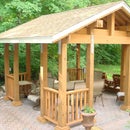

THE TREE HOUSE
9’ x 14’ House with a 5’ x 14’ Deck.
This is a major, costly, and highly rewarding project.
THIS WAS AN INTENTIONAL OVER-BUILD …
Supplies
THE MATERIALS
The materials needed for this particular project were as follows :
FOOTINGS :
(21) bags 80lb redi-mix cement
(24) 3/8” x 2’ rebar
(1) yard of ¾” stone
(3) 6” X 10’ PVC PIPE
TEMPORARY WOOD :
(24) 2x4x8 boards (Braces for Posts)
POSTS :
(4) 6x6x16 pressure treated posts (tall house high posts)
(2) 6x6x8 pressure treated posts (tall porch posts)
(6) 6x6x8 pressure treated posts (short house & porch posts)
(4) 4x6x8 pressure treated posts (wall posts)
(24) ½” x 12” galvanized bolts with washers & nuts --- (anchor short 6x6 posts and Floor Header Beam to tall 6x6 posts)
(20) ½” x 10” galvanized bolts with washers & nuts
HEADER BEAMS :
(3) 280 lbs. each : floor header beams (5+7/16” x 11+7/8” x 16’)
(2) 170 lbs. each : ceiling header beams (3+1/2” x 11+7/8” x 16’)
(16) 2x6x14 or 16 pressure treated boards --- (floor joists)
(5) ¾ x 4 x 8 plywood - pressure treated --- (tree house floor)
(16) ½” x 8” galvanized bolts with washers & nuts --- (anchor interior headers to posts)
CEILING RAFTERS :
(34) 2x6x10 or 12 pressure treated boards --- doubles up on outer ends, and one on each side of all posts
(2) 2x6x14 or 16 pressure treated boards (Ceiling rafter end-caps)
(1) 2x6x12 pressure treated board --- (ceiling fan support)
(8) ½” x 8” galvanized bolts with washers & nuts --- (anchor end ceiling rafters to posts)
(80) hurricane straps – standard straight shape
ROOFING :
(7) sheets ¾” x 4 x 8 plywood
20 lbs. of 3” galvanized nails (to nail down plywood)
(1) Roll of 100’ weather-shield roofing
(3) square shingles (usually 1 bundle = 1/3 square … fancier shingles = ¼ square)
Galvanized Roofing Nails (to nail down shingles)
(4) 2x4x12 pressure treated boards (roof peak perimeter molding)
(4) aluminum drip cap edging
(2) 4x6 Horse Stall Mats (to surround tree to keep out weather)
FRAMING :
(80) 2x4x8 pressure treated wood (house framing)
50 lbs. 3” galvanized nails … or nails for framing gun
RAILINGS :
(1) 6x6x12 pressure treated post (front porch posts)
(1) 4x6x16 pressure treated post (front porch rail top)
(1) 4x6x8 pressure treated post (front porch rail top)
(1) 4x6x8 pressure treated post (stair posts)
(2) 2x10x8 pressure treated post (stair posts)
(2) 2x6x12 pressure treated post (stair treads)
(8) 2x4x8 pressure treated post (stair treads & stair railings)
(4) 2x4x8 pressure treated post (railings)
(70) 2x2x3’ pressure treated spindles (railing)
LOFT :
(2) 4x6x8 pressure treated posts (loft posts)
(4) 2x6x10 pressure treated boards (loft frame)
(3) 2x6x12 pressure treated boards (loft frame)
(16) 2x6 Joist Hangers (loft frame)
(2) 4x8 pressure treated Plywood (loft)
(2) 4x6x8 pressure treated posts (loft stairs
(14) 2x2x3’ pressure treated spindles (loft railing)
(1) 2x6x8 pressure treated board (loft railing)
(8) ladder rungs
(3) hand rails
(1) 2’ chain and bolt (safety chain)
INTERIOR :
(16) 2x4x8 pressure treated posts (slide framing)
(16) 3” hinges (interior slide doors and trap door)
(1) hydraulic door closer (trap door)
(1) handle (trap door)
(80) 12” square rubber exterior patio mats (to carpet the interior floor)
ELECTRIC :
CONTROL BOX :
(1) square deep electric box & closed cover --- (receiving box for initial electric run)
CEILING FAN :
(1) Ceiling Fan
(1) Electric Outlet Box --- (for Fan)
(1) Electric Double Outlet Box --- (for fan light and fan switches)
(1) Fan Dimmer Switch
(1) Fan Light Dimmer Switch
(1) Double Switch Exterior Cover --- (Fan Lights and Fan)
LIGHTS :
(1) Fluorescent Light --- (lights)
(1) Electric Outlet Box --- (for lights)
(1) Light Dimmer Switch --- (Lights)
(1) Single Switch Exterior Cover --- (Lights)
OUTLET BOX :
(1) Electric Outlet Box --- (electric outlets)
(1) GFI Receptacle --- (electric outlets)
ELECTRIC LINES :
(1) 20Amp breaker --- (for main electric panel in house --- for GFI receptacle)
(1) 20Amp breaker --- (for main electric panel in house --- for Fan & Lights)
(1) square deep electric box & closed cover --- (receiving box coming out of house for electric lines)
(1) 250’ roll of BLACK # 12 wire --- (electric)
(1) 250’ roll of WHITE # 12 wire --- (electric)
(1) 250’ roll of GREEN # 12 wire --- (electric)
(15) 1” x 10’ Electric PVC pipes --- (electric lines)
(6) PVC electric box connectors --- (connect PVC pipe to electric boxes)
(10) 1” 90° PVC elbows --- (electric lines)
(6) 1” 45° PVC elbows --- (electric lines)
(1) Quart of PVC Cement (glue) --- (electric lines)
(20) 1” pipe clamps
1 lb. 1+½” galvanized nails
GUTTERS & LEEDERS :
(3) 10’ gutters
(18) gutter braces
(2) boxes of gutter brace screws
(2) downspout connections
(2) 10’ leeders
(6) 45° elbows
(6) Leeder clamps
(1) box ¾” galvanized screws
SIDING :
(12) boxes Smoothe Cedar Shakes
20 lbs. galvanized shake nails
STAIN :
4 Gal. Stain ... Rollers ... Paint Brushes
TARPS : several
TOOLS NEEDED
Cement Mixer ... Cement Mixing Tub ... Hose for waterline
Post Hole Digger (or backhoe)
Shovel ... Pick ... Rake ... Hoe ... Breaker Bar
Hand Level – small (10”) & Large (3’) ... Laser Level
Square – Large ... Square – Small ... Crowbar
Hammer ... Ratchet Set ... Pliers ... Pipe Clamps ... Wrench
Step Ladders (2) ... Scaffold Walkway ... Buckets ... Broom
Box Cutter ... Caulk Gun ... Screwdrivers (Phillips) ... Rasp
Hand Chisels ... Sander ... Paint Roller ... Paint Brushes
Stapler (½” staples) ... Chalk Line ... Circular Saw ... Miter Saw
Reciprocal Saw ... Jig Saw ... Hand Saw ... Router ... Drill
Tape Measure ... Straight Edge 3’ ruler ... Angle Ruler
Drill Bits : ½” x 12” long
Framing Nail Gun --- for 3” nails
Roof Nail Gun – 1+¼” nail stapler for Roof Shingles (alternative : you can use a hammer)
3” Nail Gun – for Roof Plywood (alternative : you can use a hammer)
3+½” Palm Nailer (for hard to hammer nail areas)
Compressor (to run Palm Nailer, Framing Gun and Roof Nail Gun )
Step 1: THE STEPS IN a NUTSHELL
Secure the Basic
Structure :
1st Set of Short Posts :
1) Dig all 6 Holes
2) Pour Cement
3) Insert the 6 8’ Posts in holes, supporting them upright temporarily with 2x4’s
4) Laser Level all posts … make certain they are square, and diagonal measurements are accurate
5) Connect temporary support boards to hold all posts tentatively in place
6) Re-Laser Level and mark all 6 posts where Header Beams will rest
7) Remove the 6 posts and cut where the Header Beam will sit
8) Re-install these 6 Posts … with their 12” x 12” PVC pipes around their base
9) Re-Laser Level all 6 posts, and verify all 3 main Floor Header Beams will be level with each other later
2nd Set of Tall Posts :
10) Install 4 16’ 6x6 posts for the House and 2 8’ 6x6 posts for the Porch … bolt them to the 1st set of Posts
11) Connect temporary support boards to hold all posts tentatively in place
12) Re-Laser Level all posts, and verify all 3 main Floor Header Beams will still be level with each other
Floor Header Beams and Floor Joists :
13) Install the 3 Floor Header Beams
14) Install several temporary Floor Joists (perpendicular to header beams) to prohibit lateral movement
15) Re-Laser Level all posts and all 3 main Floor Header Beams to verify everything is still level & square
16) Bolt the 3 Main Floor Header beams to all 6 sets of Double Posts
17) Lay several Floor Joists across all 3 Header Beams and verify its Level
18) Bolt 1 Floor Joists to the inside of each of the 3 sets of double posts (running from House section to Porch)
19) Install all Floor Joists
20) Install the Porch floor boards
21) Install the Porch railing after cutting the 8’ posts to size
22) Fill in the holes
Wall Beams, Ceiling Header Beams, and Ceiling Joists :
23) Cut 4 6x6 Wall Posts to the desired height (7’) and bolt to the main posts
24) Install 2 14’ Ceiling Header Beams on top of the Wall Posts, and bolt to the main posts.
25) Install Ceiling Joists across the Ceiling Header Beams, 1 on each side of posts, then bolt to main posts
There will be no more Ceiling Joists used, as the Tree House Roof is an ‘open-air’ concept.
Ridge Posts, Ridge Beam, and Ceiling Rafters :
26) Determine the desired Roof Height, then verify the ‘roof pitch’ is within acceptable limits
27) Determine where Ridge Beam will be located
28) Measure and cut the Pidge Posts, and bolt them to the double Ceiling Header Beams
29) Install the Ridge Bean onto the Ridge Posts
30) Install the Ceiling Rafters
Roof :
31) Frame out the Skylights
32) Install Plywood
33) Install Skylights
34) Install Weather-shield
35) Install roof shingles
Framing & The Slides :
36) Install plywood on floor
37) Frame the stairs to the Porch
38) Frame the Loft
39) Determine location of slides
40) Frame the walls for the Slides
41) Install the Slides
42) Install the Firemen’s Pole
43) Install the Rock Climbing Wall
44) Frame the walls for the Windows and Doors
45) Install sheathing on the sides of the Tree House
Finishing :
46) Install Windows
47) Install Doors
48) Install cage around the Tree
49) Install Trap Door
50) Install Workbench
51) Install Shelving
52) Install Fence and Ladder for Loft
53) Install interior doors for Slides
54) Install Siding
55) Stain Siding
Electric :
56) Run underground Electric from main residence to Tree House, with outside shut-off controls
57) Run electric and install Outlets.
58) Run electric and install Lights
59) Run electric and install Ceiling Fan
Finish ::
60) Walk up the stairs, sit on the Porch and have some lemonade !
Step 2: TOWN BUILDING REQUIREMENTS
Out of the Dog House and into a Tree House … I needed an escape ! … The grandkids did too !
My Town required a building permit. Their requirements are that a Tree House, no higher than 15’, can be built as long as NO part of it touches a tree … therefore my Treehouse is a house and deck surrounding a Tree !
Disputed building requirements --- The town required :
1) cement at least 12” wide x 36” deep to ground level,
2) post cleats on top of the cement pads to secure the upright ground posts,
3) 4 3+ ½’ 6x6 ground posts supporting the main floor header beams and bolted to the post cleats,
4) 2 12” high x 14’ long main floor header beams on top of ground posts,
5) 4 5+ ½’ 4x6 wall posts on top of the floor header beams,
6) 2 12” high x 14’ long ceiling header beams on top of the wall posts,
7) roof rafters on top of ceiling header beams.
I thought the above building requirements to be a house of cards and structurally unstable. The town was persistent in adhering to these requirements, but agreed to the additional inclusions of mine, as follows :
SOLUTION :
I would put a house high Post 13+ ½“ high 6x6 alongside each of the 4 sets of the Town’s required Ground and Wall posts and a 9+ ½‘ high 6x6 alongside each of the 2 Deck posts, and bolt them together.
For the cement footings, I would put cement 18” high x 24” wide with rebar at the bottom of a 42” hole (not filling the entire hole with cement), and both the town’s post requirements and MY additional posts would sit on top of this cement pad side-by-side, with 12x12 PVC pipes around both 6x6 posts (now 6x12 posts), with the PVC pipes rising 2’ above the ground to resist water.
The town approved the cement base idea as long as PVC pipes were installed to provide protection of the posts from the ground rot concern.
The OK was given to build … (this double-post compromise proved to work quite well during construction, and was needed).
Step 3: TERMINOLOGY

*) MY House High Post ... the 4 solid 6x6 posts from ground level up to roof (16' high, and later trimmed as needed) … items 2, 3, 4, 5, 6, 7 are Bolted to these Posts ... 2 6x6x12' posts used for porch (and later trimmed as needed)
1) PVC Pipes ... (around both MY house high Post and Town’s Ground Post)
2) Town’s required Ground Post ... (supporting Floor Header Beam) ... the short 6x6 posts approx 5' high that are 2' in the ground and approx 3' above ground ... these are the posts the 3 Gluam Floor Header beams rest on.
3) Floor Header Beam ... (on top of Ground Post) ... the 3 Gluam beams supporting the entire structure ... the Floor Joists rest on these beams
4) Floor Joists ... (on top of Floor Header Beam) ... the horizontal beams laying on top of the Gluam Floor Header beam ... the floor rests on the Floor Joists
5) Town’s required Wall Post ... (on top of Floor Header Beam) ... the 7' post supporting the Ceiling Header beam
6) Ceiling Header Beam ... (on top of Town’s required Wall Post) the horizontal Gluam beam supporting the Ceiling Joists
7) Ceiling Joists ... (on top of Ceiling Header Beam) ... the top horizontal beam in the picture
Step 4: The Footings


The Tree : a 100’ Oak Tree, is designed to be in the MIDDLE of the Tree House, and extending through the roof.
The 42” deep ground holes were made with a backhoe wherein no tree roots were encountered since the Oak tree had roots going straight down vertically, and were not spread out horizontally as in most other tree varieties.
The town’s required Ground posts were placed on 18”H x 24”W cement pads at bottom of 42” hole (a 24” wide cement pad base allows room to maneuver the posts around for proper measurement and alignment.).
Temporary supports double as leveling boards to hold the posts in place.
Initial desired Ground Post height was approx. 5+ ½‘ high (2’ below ground + 3+ ½’ above ground level).
Depending on the topography of the land, the height of each post will vary, so allow extra height in the beginning … the top of all Ground posts will be adjusted later when they are squared and leveled with each other, before being cut to size.
Lowest desired height from ground level to top of Ground post is 3+ ½’ … 3+ ½’ post height + 12” floor header beam + 6” floor joist = 5’ floor above ground
Picture # 2
The 4 Ground posts in the foreground are for the House section …
the 2 Ground posts in the far ground are for the Deck.
Step 5: Squaring the Posts

SQUARING is the next step, and MUST be performed before construction continues … described as follows:
With the cement pads in place, placement of the Ground posts with temporary supports allows the posts to be moved around for exact measurements.
It is absolutely CRITICAL that you take time to make certain the post Distances and Levels are exact, especially the DIAGONAL measurements … BEFORE YOU CONTINUE … otherwise the entire structure will not be square ( Square means built at accurately measured 90° right angles )
See the picture above ...
IF THE GROUND POSTS BEARING THE WEIGHT OF THE FLOOR HEADER BEAMS ARE SQUARE … CONTINUE :
Step 6: Installing the Posts


Picture # 1
The 6 sets of double posts (town’s Ground posts + my House High posts) were inserted into PVC pipes, Ground posts were re-measured and re-leveled, then both posts were bolted together. With all posts level and square, floor headers beams are installed and bolted. 2 floor joists are bolted to the posts for lateral stability. The dirt is filled into the holes, and the PVC pipes are filled with Pea gravel for stability and drainage.
Picture # 2
See the Tree … it is right in the middle of the Tree House.
The 14’ post span to stay clear of the tree required 3 floor header beams. They are each 5+ 7/16” thick, 11+ 7/8” high x 16’ long Treated Rosboro Gluam beams @ 280 lbs. each, and are intended to extend 1’ out on each side of the 14’ house and deck floor.
Note the 4 House High posts, and the 2 high posts for the deck.
Step 7:

SPECIAL NOTE: you can replace Gluam Beams with sufficient # of 2x12x16 boards, if center supports are possible.
If the posts, floor header beams, and floor joists are not totally level and square by now, make any necessary adjustments before proceeding or start over.
Step 8: Installing the Ceiling Header Beams


Picture # 1
All 2x6 x 14’ Floor Joists now installed on top of floor header beams
Picture # 2
7' Wall posts installed and bolted to my 16' House High posts.
The 3+ ½“ x 11+ 7/8 “ x 16’ Treated Rosboro Gluam ceiling header beams @ 170 lbs. each are now installed on top of Wall posts, and bolted to my House High posts ... (The 14’post span also required these header beams.)
Picture # 3
View of the Gluam ceiling header beams sitting on the town’s required Wall posts … both are bolted to my 16' House High taller posts. Double 2” x 6” x 10’ ceiling joists rest on the ceiling header beams and are also bolted to the posts (looking left to right).
The Upper frame is now secure and ready to build on.
Picture # 4
2 self-proclaimed construction inspectors … WHAT DID I DO ? ... I’m the good looking one !
Gluam Beams were needed to span the 14’ unsupported gap :
Weight of Gluam Beams :
170 lbs. each : ceiling header beams (3+1/2” x 11+7/8” x 16’)
280 lbs. each : floor header beams (5+7/16” x 11+7/8” x 16’)
Tractor with bucket/fork-lift used to raise and set floor header beams in place.
3 people needed to raise ceiling header beams in place, using a series of several step supports (tractor could not raise that high)
xxxxxxxxxxxxxxxxxxxxxxxxxxxxxxxxxxxxxxxxxxxxxxxxxxxxxxxxxxxxxxxxxxxxx
SPECIAL NOTE: you can replace Gluam Beams with sufficient # of 2x12x16 boards, if center supports are used … but extra Ceiling Joists may be required to counteract the pressure on these boards by the roof due to the ‘open ceiling ’ used here.
Step 9: Flooring

Plywood being installed on the house floor. 1x6 floor boards now installed on porch.
Note the 12” bolts connecting the 2 6x6 posts … this is done everywhere throughout the structure.
Step 10: Basic Frame Finished

Finished structure to this point.
With the double-posts bolted and being 2’ underground, and with all other framing also bolted together, the structure is very solid.
Now anything, particularly the roof, can be built on top of it without worrying about any stability issues.
Step 11: THE LOFT

A 5’ High Loft was inserted in the inside of the House. Later, a ladder will be added.
This can be used for resting, sleeping, watching videos, playing, etc.
Visitors have an area to camp out underneath.
It was beneficial during construction, for now it doubled as a work platform.
Step 12: THE ROOF

The Tree splits into 2 trunks … no problem … there will be 2 holes in the roof !
The Roof is easy to frame … 2 Ridge Posts are the key … they sit in the middle of the double Ceiling Joists at each end of the structure. The Ridge Beam then runs between the tree trunks and rests on top of the Ridge Posts.
Ceiling Rafters are later connected from the Ceiling Header Beam to the Ridge Beam, and capped with plywood.
Ceiling Joists are only used at the 2 ends of the Tree House ... they are not used in the middle of the Tree House in order to have an 'open ceiling' concept ... the very sturdy Gluam Ceiling Header Beams will support the Ceiling Rafters going to the Ridge Beam just fine !
xxxxxxxxxxxxxxxxxxxxxxxxxxxxxxxxxxxxxxxxxxxxxxxxxxxxxxxxxxxxxx
The Pitch of a roof is its vertical 'rise' over its horizontal 'span' … i.e. : the higher the Ridge Beam the steeper the roof Pitch will be. The Pitch is expressed in terms of the # of inches a roof rises Vertically over a 12” Horizontal span … ex: a 4” rise = a 4/12 Pitch
For proper water drainage, a Pitch of 2/12 is the minimum required for shingles and roll roofing, with 4/12 and higher being standard.
Ridge Beam height is really whatever your design calls for, as long as it’s above the minimum required Pitch. The desired height of the Ridge Beam often determines the Pitch … the desired Pitch can also determine the height of the Ridge Beam. Generally both are considered in determining a reasonable Roof height. My desired height was 30”.
Calculating the Roof Pitch :
Ridge Beam is 30” high (its vertical rise) above the Ceiling Joists, and is located 5’ (its horizontal span) from the far outer edge of the Ceiling Header Beams … the Pitch is calculated as 30” / 5 = 6” … = 6” vertical rise for each 12” horizontal span … for a 6/12 Pitch.
I am above the required minimum Pitch of 2/12, wherein my 6/12 Pitch is acceptable to me. Let’s erect the 30” high Ridge Beam …
THE RIDGE POSTS :
Ridge Beam sits on top of Ridge Posts, which were installed to support the Ridge Beam. It provides for a secure and easy installation. Ridge Post height is generally measured from the top of the support wall it rests on … to the bottom of the Ridge Beam it supports.
Here a basic Ridge Post of 22+½” is needed (30” from support wall to top of Ridge Beam, less 7+ ½” for height of Ridge Beam).
This measurement was extended by 19” to accommodate : 1) the bottom of the Ridge Post is extended 11+½” … 5+ ½” down between the double 2x6 Ceiling Joists … plus an additional 6” below it for extra support and design, and 2) the Ridge Post is extended 7+½” to the top of the Ridge Beam in order for the Ridge Beam to sit flush in notches cut in the center of the Ridge Posts for extra support.
My over-built but very secure Ridge Posts now measures 41+½” (22+½” basic height + an extra 11+½” down + an extra 7+½” up).
Note : the 22+½” basic Ridge Post height still supports the Ridge Beam, with the extra 19” only providing extra support and design
With scaffold in foreground and Loft in background, construction of the Ridge Posts and securing the Ridge Beam proved very easy.
xxxxxxxxxxxxxxxxxxxxxxxxxxxxxxxxxxxxxxxxxxxxxxxxxxxxxxxxxx
During construction, the tree’s double trunks posed a clearance problem, and the center location of the Ridge Posts had to be moved a little to the Right, which made the roof look a little lop-sided … resulting in a 6+½/12 pitch on the right and a 5+½ /12 pitch on the left.
Then again, this is a Tree House, and the lopsided design actually made it very nicely unique … I tell everybody that it was planned for in my original design, and everybody likes it ! (score 1 point for me !)
Step 13:


Picture # 1
Here the Ridge Beam is installed onto the 2 Ridge Posts and sits flush into them.
Notice the massive size of the supporting Ridge Posts (7 2x6’s) … this was done for both tremendous support strength and design.
Picture # 2
Note how the double Ceiling Joists have themselves be doubled with a 2nd 2x6 on each side of the original double Ceiling Joists.
Notice how the Ridge Post consists of 7 2x6’s : 3 are placed through the now 2 double 4x6 ceiling joists, with 4 more sitting on top of the ceiling joists to distribute the roof weight onto the joists and not allow the Ridge Post boards between the joists to slide down.
Note how the Ridge Post extends 6” below the Ceiling Joists … this was done both for increased support and design.
The Roof Rafters are now installed. Notice how the split of the Tree Trunk goes through 2 points in the roof.
Skylights are also framed out.
This is turning out to be a ‘real’ Tree House !
Step 14: THE FRAME


The floor level is 5’ abound ground level. A higher elevation was not desired in case kids fell off the Tree House … at least at this height they would lightly bounce !
Picture # 1
South and East views : The basic Frame is now completed , Now ready for the sides next. 1st of 3 slides attached to outside of house.
Picture # 2
North view … Front slide attached. View of Porch …
Step 15:


Picture # 1
Inside view of back slide … view of Ceiling Header Beam sitting on top of town required post and bolted into my additional post.
Rear tube slide portal framed and slide attached to outside of Tree House so it would not intrude into the inside of the Tree House.
Picture # 2
Close-up view of rear tube slide installation (Note 2x6 slide supports under slide). Height determined by slide elevation requirements.
Step 16:


Picture # 1
The remainder of the House framing is now being installed. Window dimensions match window specifications.
Note the 4x6 railing cap in the background.
Picture # 2
Stairs now installed … a very time consuming project.
Note 2x4 railings (these did not meet town requirements later on … need to be hand width only … i.e. a 1+ ½” pipe was added.
Step 17:


Picture # 1
View of the remainder framing.
Picture # 2
View of the remainder framing.
Step 18: THE SLIDES

Slides were an extra novelty added to the Tree House. One straight Tube Slide, 1 360° turn Slide, *1 Straight Open Slide, *1 Firemen’s Pole, and *1 rock climbing wall were added. To protect both the Tree House and to prevent animals from climbing into the Tree Horse, Slide Doors were later installed inside the Tree House.
* = not shown in this picture
Slides purchased from outdoor playground vendor who sold the slides separately as repair parts to customers … they were readily sold separately.
Step 19:


Pictures # 1 & 2
Stairs installed inside the Tree House to easily step into the rear straight Tube Slide. Slide set high due to minimum height requirements of the slide.
Picture # 3
360° slide interior portal framed.
Slide to left eventually put in front of Tree House. This doorway later used for Firemen’s pole portal.
Step 20:


Picture # 1
Loft windows framed … will have permanent solid plastic panels as its windows.
Picture # 2
A small Rock Climbing Wall installed on South side of deck.
These items also available from playground vendor.
Picture # 3
Firemen’s Pole installed in a separate doorway next to 360° slide.
This item also available from playground vendor.
Step 21: SIDING


The Tree House now gets a layer of ¾” CDX plywood, and Cedar Shake siding stained with clear preservative.
Step 22:


Windows and Doors get their trim. Note small ‘escape’ door on lower right. Note protection ‘Cage’ around the Tree.
The roof was shingled at the earliest convenience in order to protect the Tree House (before doors, windows and interior is done).
Step 23: INTERIOR


Finishing touches are now made to the interior of the Tree House.
Picture # 1
The straight tube slide receive steps to easily get into it.
¾” Patio type rubber mats laid on entire floor.
Underground electric run to Tree House … outlets and switches.
Portable heater (not shown) makes it cozy in winter !
Picture # 2
Doors installed around straight tube slide opening.
Doors needed for privacy, weather protection and animal safety.
Picture # 3
Protective cage installed around base of tree.
Picture # 4
Trap door with hydraulic door closer installed and a 5’ ladder.
Step 24:


Picture # 1
Plastic panels installed in loft window portals.
Picture # 2
Loft railing installed.
Picture # 3
Loft ladder installed, obtained from playground vendor.
Picture # 4
Tempered glass installed throughout … if broken, glass will crumble into small granular pieces instead of sharp panes.
Step 25:


Picture # 1
A collapsible workbench is added.
Picture # 2
Shelving and seats are made. Laminated board put on workbench.
Picture # 3
Electric light installed over workbench.
Picture # 4
Variable speed Ceiling Fan and dim-able light installed.
Nice touch for summertime !
Step 26:


Picture # 1
View of the Firemen’s pole and the 360° slide portals.
Picture # 2
Directly under the Loft, Doors for Firemen’s pole and 360° slide installed.
Doors needed for privacy, weather protection and animal safety.
Step 27: DOORS & WINDOWS


Doors are all hand-made, while all windows are tempered glass for safety.
Step 28:


Pictures # 1 & 2
½” Plywood with ¼” plastic sheets front and back. ¼” plastic Tree and leaf cutouts were inserted into wood cutouts. Stained Glass paint used to color plastic cutouts --- the kids made this !
Pictures # 3 & 4
Skylights are tempered glass for safety (skylights are fixed … do not open).
Step 29: THE FINISH

Roof shingles on. Wood stained. 4’ x 6’ rubber horse stall mat cut and fitted around tree to keep most of weather out.
Step 30:

Tree House is close to principal residence, but far enough away to be adventurous.


