

Introduction: The Hands of TIme


The Hands of Time Nixie clock started out as an idea to make a clock that was more artistic than clockish looking as there are many clocks out there that lack character but in saying that there are a good few that are works of art displaying some fantastic skills and imagination from their creators.
Me? I am quite good with a sledge hammer and try to not be all fingers and thumbs when it comes down to it.
The Hands of Time, along with the Atomium Mk II, must be the most accurate work I have managed to create without screwing it up!
I have not gone into the electronics or the brass machining as I have covered these in previous Instructables. If you check the ones I have posted alread you will get a good description of what needs to be done.
OK, on with the show!
Step 1: The Bits Required and the Tools Needed to Do It!

Materials listing of the Hands of Time
6 x 75mm Solid Hardwood Beech Balls
Beech Plank
2 x 12" Artists Wooden Modelling Hands
6 x ZM1020 Nixie Tubes
6 x B13B Remote Sockets
6 x 3mm Red LEDs
2 x 3mm Orange LEDs
A heck of a lot of 28 AWG Insulated Wire
1 x DINK Remote Wiring Clock Board
3mm Heat Shrink Tubing
1" x 1/8" Brass Strip
14mm Round Brass Bar
200mm x 8mm Brass Tube
6 x 1 1/4" Plumbing Olives
6 x 3/4" Brass Flange Nuts
4 x 4mm x 40mm wood screws
4 x Brass Screw Washers
4 x 3mm x 12mm Brass Cheese Head Screws
4 Circuit Board Stand Offs made from Aluminium Hex Bar
4 x 3mm x 16mm Brass Cheese Head Screws
1 x Custom Engraved Name Plate
1 x Hardwood Ball Jig - see text later
Tools required for construction
Hobby Lathe
Hobby Milling Machine
Forstner Bits
Dremel
3mm drill
8mm Spot Weld Removal Drill
Buffing Wheels
Soldering Iron
Small Pipe Cutter
Round FIle
WIre Strippers
Tweezers
2 x Quick Clamps
Hot Glue Gun
Hot Air Gun
No2 Pozidrive Screw Driver
Multiple Grades of Sandpaper
Cellulose Spray in an aerosol can
Two Part Epoxy Glue
Step 2: Machining the Wooden Balls.


When you design something that is not straight or flat you can run into issues so to get over the issue of accuracy I made a ball holding jig from 3 pieces of MDF and 4 screws. I later modified it to threaded rods and nuts, wing nuts would have been better!
The jig was drilled with all 3 sections screwed together using a 50mm Forstner bit to cut through the top 2 sections before taking it apart to chamfer the edges that would be in contact with the wooden balls. Reassembled and lined up against the 50mm cutter again it was then clamped to the bed of the milling machine with the table locked in position.
Drilling the first ball was the test for it and it worked fine!
The holes in the balls are drilled out with Forstner bits starting with the smallest diameter and the deepest hole for the recess followed by the larger sizes in order. The second drilling widens the hole and is also the step that produces the internal step that the socket rests on. This is followed by the largest hole for the brass insert that sits flush with the surface of the wooden ball.
This is repeated for the remaining balls to provide the recesses for the nixies and the brass inserts.
The next step is to fashion the arc of the balls as they would rest between the hands that support them. A very technical method of creating the arc was used - the biggest paint tin I had in my workshop!
To get the contact point of the balls I separated them and put doubled over carbon paper between them before knocking each one against its neighbour as it was held against the paint tin. The point of contact is critical as that is where the ball is drilled for the insertion of the 8mm brass tube that holds them in the arc.
Back to the milling machine and the ball clamp! "Ooh, Matron!" (British Comedy from the 60s & 70s)
I used a center drill as the indicator over the contact point and the face of the ball was set against a square to ensure that the hole would align perfectly. Once this was done the ball was clamped in place with the now modified jig, pilot drilled and then final hole drilled with a spot weld removal drill, this gives a good cut in hardwoods. I repeated this process for all of the contact points on the balls drilling into the recess created earlier.
Step 3: Making the Base Section.


The plank of Beech I got had a natural edge and a discolouration to it so after a bit of machining it was reduced in size and squared off on all faces to leave a reasonable piece to work on.
The position of the circuit board determines where the recess is made in the underside of the plank as the buttons have to be accessable when mounted. I have always used Forstner bits for roughing out recesses in wood as they provide a very clean hole with dimples in the base of it. So it is chain drilled to 3mm short of the required depth and about a millimeter short of the final size of the recess.To get rid of the dimples from the Forstner bit and finish off the recess sides I use a milling cutters to remove the final 3mm of wood to get the desired depth and then run it around the edge of the recess to finish it off.
Another recess has to be made on the back of the base section and this is done with slot drills and milling cutters for accuracy as the brass plate has to sit in an insert over the rear recess.
The holes for the mounting of the hands are also done at this stage based on the arc of the balls. I clamp the balls to the hands to get the measurement of the mounting holes and these are then drilled right through the base section. To get the wiring from the hands to the circuit board a channel needs to be cut from the hand hole to the recess with a milling cutter.
Another two holes are required from the front face through to the channel just created for the AM/PM LED indicators wiring. These holes are stepped to set the height of the indicators.
The final task in the base is to make a recess for the brass covers that hide the electronics and prevent curious fingers getting a nasty shock! The same process as the step of the rear control plate is used to do this.
Step 4: Let's All Join Hands!


Still interested?
OK, so now it is time to put the three different wooden parts together so that it looks like it was meant to be.
The hands get a wooden 'bone' inserted into the wrist part to fix them to the base, this has a hole drilled in the middle and up into the palm of the hand where it will contact the balls. The hands are inserted into the holes in the base and aligned with each other. The tricky bit is to get the contact point of the balls with the hands and everything level at the same time. Quick clamps are an essential here to hold things together and the ones I use are ideal for this.
The balls are clamped to the hands and levelled off. Once level I put a support in the middle as you need to remove a clamp at a time and put carbon paper between the hand and the ball to mark the contact point. Tricky to say the least but patience is required for this and it pays off. Once the contact points are marked everything is taken apart and the holes drilled for the brass tubes between the hands and the balls.
So now that everything will go together for the final assembly the dreaded wiring of the balls needs to be done.
This is no easy task as the wiring has to be soldered to the tube bases with the minimum of slack wire in order to get everything to fit in the recess for each tube. As I included LEDs to back light the tubes there are a lot of wires! Luckily the design of the electronics allows for 'daisy chain' wiring of the bases as it uses a multiplex system to power the tubes. Altogether there are 13 wires from the circuit board to the tubes and the daisy chaining allows me to feed half the wiring from each end of the ball arc but there are still 13 wires going from ball to ball and a real pain in the proverbial!
With the wiring in place and the brass tubes epoxied to the balls it is time to apply the cellulose lacquer to the wooden parts. It took about 5 or 6 coats to build up the depth of finish I wanted, it also takes about 3 days to get the last coat hard enough to be subject to the assembly stage.
Now it is time to align and secure everything together. The wiring is fed through the hands and epoxy applied to the contact area then the hands are fitted into the base section
A plate clamped to the face of the balls and the back of the hands makes sure that they are aligned and held until the epoxy sets. At the same time this plate is aligned with the base section to make sure that the tubes will be in the best viewing position. Epoxy and screws hold the hands to the base for added security
Step 5: Feet, Cover and Plates


I made the feet from the cut offs from the plank by turning them down and fitting a brass olive that had been polished up. These were fitted to the base with wood screws and brass inserts in the holes that resulted from the turning process.
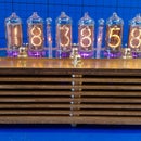
The cover for the base was made from 0.5mm brass sheet in 3 parts for simplicity and screwed to the base section. Another two plates were put on the ends of the base as the grain did not come up to scratch after being lacquered.
The inset brass plate for the controls of the clock was machined to allow the buttons to protrude and a couple of shrouds made from the 14mm brass rod makes the power and GPS inlets look better than just holes.
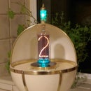
The AM/PM indicators are from 14mm brass round bar as well and are filled with epoxy to give a diffused light from the LEDs.
Step 6: Wrapping Up.

I get a lot of pleasure from making Nixie Tube clocks and try to be original in my ideas. I am by no means an expert at them and I am envious of some of the ones that are out there and have been featured as Instructables.
All you need to create something is imagination and a bit of ingenuity, if it does not go right the first time find out why and go for it again. You learn by experience.
If you got this far in this instructable, my thanks for your perserverence!

Participated in the
Woodworking Contest 2017

Participated in the
Lights Contest 2017


