

Introduction: An Arduino Final Countdown Timer With Wireless Programming


//If you can't tell, the fifth picture(gif) shows that the "Final Countdown" Timer's LED is fading//
**Don't be shy to click on the pictures to get more descriptions throughout this tutorial.**
What does it do?
- It's an enhanced kitchen timer that can turn off any device that you would normally plug into the wall outlet. But when there are 19 seconds left, the Arduino will play Europe's "Final Countdown" song, just like in the Geico commercial!
- It takes advantage of the "Multitasking ability" of the Arduino by using the millis() function(I will explain this later).
- It will fade a LED, listen to whatever the user types via Bluetooth, and play music all at the same time.
- You can upload code to the Arduino wirelessly via Bluetooth.
Difficulty:easy..We will be reading schematics and reprogramming a Bluetooth module!
Preface:
Before starting this project, please acknowledge the one who taught me the "secrets to multi-tasking" to enhance this project. Special thanks to the Bald Engineer for the FadeWithoutDelay Code(void doTheFade()) See this LINK for more information.
Special thanks to "Europe-The Final Countdown" for creating a song that was quite easy to configure through code.
First, check out the three videos above.
Note:**The Final Countdown Song is heard near the end of the first video**
Why is this Arduino project unique than any other relay switch? It's because it does not use the delay() function at all(This is a very good thing)!
**Why not use delay, and what is it? Don't worry, I'll explain that in the next step.**
WARNING
WE WILL BE DEALING WITH Alternating Current(AC) so make sure you get adult supervision.
Story Time:
(The Second Video) One day, I was playing slither.io just after completing my homework. While I was playing my game, my Dad asked me to turn on our wet grinder for exactly 45 minutes. And that's when it hit me like ice cold water being thrown on my back. I asked myself, "Why don't those Indian marketers add a timer that would automatically turn off my Grinder?"

**A wet grinder is basically a big smoothie mixer, but instead of blades it uses cone-shaped granite stones to ground rice into dough**
Unfortunately, this model doesn't come with a timer(just an on and off switch).
This is what a wet grinder can make if the rice is ground properly:

It's called Dosa. And it looks scrumptious!
Realization:
That's when I thought about making my Arduino Uno turn off the grinder for me. After all, robots have a better reaction time than us humans. Personally, I just want to focus on playing slither.io and get to the top ranks, but not miss the right time to turn off the grinder.(Trust me, I play pretty good when no one's watching).
During this project, I thought I would make things a little more interesting; I decided to make a delay-free project.
And to make it even more special, I decided to ignore using physical buttons and LCDs(Liquid Crystal Displays) in the project. Instead, I wanted to use my reliable phone to set the timer!
Bonus Feature:
This project also includes a bonus feature that I hope you will use everytime you hit that upload button: Wireless programming. It does not consist of a shield because I know from personal experience that some Arduino boards are not shield-friendly. So I took the honor of creating a simple and more efficient circuit for the wireless programmer. It is a little similar to the wireless programmer on the Make website, but I took out some unnecessary components and saved a whole lot more physical space.
Why use wireless programming?
- Why not. I mean this is the future, and if you think my Arduino code could be better you can always upload code to the Arduino in a tightly locked place with no access to USBs. (Or if you are too lazy to disconnect and reconnect the USB to reprogram)

Step 1: Multitasking Vs. Arduino's Delay Analogy
Multitasking
- The main goal is to fade/blink a LED, play music, and allow the Arduino to listen to whatever the user inputs via Bluetooth all at the same time. How is this even possible? Answer: Multi-task the Arduino!
- Okay, you got me; it's called making an illusion with multi-tasking. You see, computers(like the Arduino) don't multi-task, instead, they do everything one line of code at a time, but they do it really really fast using a clock, thus looking like they can multi-task! You might hear people say overclocking a CPU. This basically makes your CPU more reactive to the clock, thus giving a higher processing power. The clock is what the CPU bases itself off of to keep track of how fast it should process data from one location to another and make an action.
- It's kind of like your child yelling, "Are we at home yet?" every second, and you say "no we aren't". But there is a small window of time when you say "we are there"; if the child misses the small window of time by even 1 second, you will still say "we are not there" and continue to drive on the road past your house(Which sound ridiculous, but stick with the analogy).
When you say "we are there" and enter your house you have just made an action while monitoring everything else in the car, such as the headlights, the horn, speaking to your child all at the "same time" or in sequential order at a really fast rate. This is exactly how the millis() works.
- It's kind of like your child yelling, "Are we at home yet?" every second, and you say "no we aren't". But there is a small window of time when you say "we are there"; if the child misses the small window of time by even 1 second, you will still say "we are not there" and continue to drive on the road past your house(Which sound ridiculous, but stick with the analogy).
- Okay, you got me; it's called making an illusion with multi-tasking. You see, computers(like the Arduino) don't multi-task, instead, they do everything one line of code at a time, but they do it really really fast using a clock, thus looking like they can multi-task! You might hear people say overclocking a CPU. This basically makes your CPU more reactive to the clock, thus giving a higher processing power. The clock is what the CPU bases itself off of to keep track of how fast it should process data from one location to another and make an action.

Arduino's Delay
- Now there is this dirty function, as I have said early, named delay(). What's wrong with it?
- Using the same analogy as before, if you were to use delays you will make it to your destination, but you can't do anything else along the way. So in Layman's terms, you will continue to drive from a random location to your house in a straight line; you will drive through everything in your way at a constant velocity because you can't stop or turn(or even put a signal indicator) because delay forces you to wait and stare at the clock 'till the time comes to make an action.
- It's kind of like how you would stare at the clock(at work or at school) and start to get excited for the day to end. You are focused on ONE THING ONLY: the clock!

Conclusion
- So the more frequently the child yells(Kids, please don't do that), the more chances you might say "yes" in that given window of time and go in your house. Therefore, the faster the computer's reaction time, the faster the processing power(And the fewer uses of the Arduino's delays causes a faster reaction time).
- In fact, if we get rid of the delay(), we can make a computer. But let's not get ahead of ourselves, the Arduino Uno's clock speed is 16Mhz, while an i7 core processor, on most Windows computers, is 2.4Ghz. So yeah, it's a HUGE difference. Therefore, the Arduino can get a little laggy if you load it with too much data to read.
- Too much lag can be created by fading a LED and playing music at the same time because both OUTPUTS require consistent clock readings from the millis() .
- But, reading from Bluetooth while fading a LED or playing music is fine.
- In fact, if we get rid of the delay(), we can make a computer. But let's not get ahead of ourselves, the Arduino Uno's clock speed is 16Mhz, while an i7 core processor, on most Windows computers, is 2.4Ghz. So yeah, it's a HUGE difference. Therefore, the Arduino can get a little laggy if you load it with too much data to read.

Main Purpose:

As many of you beginners to Arduino know, you like to use delay(). This is a big NO, NO, NO!
The goal of this project is to influence my fellow tinkerers to avoid using delay() and this massive project should be an example of that. When you use delay, you stop the entire Arduino until the given condition is complete. For example: If you wanted to blink a LED every second, the easy way would be to delay(1000). But this is so inefficient because if you wanted to play music while blinking a LED, you simply can't, so you are forced to multi-task the Arduino.
So you realize you want your robot to do some things at the same time. This may be hard at first, which is why it is always helpful to have a piece of paper beside you to sketch your plan. Anyway, the one main function I want you to learn is the millis() function and how to use it to do some other cool and unnecessary stuff at the same time.
So get ready "to ditch the delay and look at the clock", as my boss once said!
Step 2: Gather Tools


You will need these tools:
- A pencil with an eraser(You find them at school)
- A soldering Iron Link
- Some solder Link
- Electric Tape (From your local hardware store or Walmart)
- Scissors(You can find them in your kid’s backpack or Walmart)
- Wire cutter(From your local hardware store or Lowes)
- Tweezers LINK
- A mini Hot glue Gun(Amazon or at Hobby Lobby)
- A Power Drill(At your local hardware store or Walmart)
- With Drill bits for different size screws
- A flat head(-) screwdriver
- A Phillips(+) screwdriver
- A wire trimmer(at Lowes)
- An X-Acto knife(at Walmart)
- A table to do all this stuff on.
- A computer(Mac or Windows) with Bluetooth capabilities(or Bluetooth dongle)
Step 3: Gather Materials for Wireless Programmer


Alright, the ingredients to the Wireless programmer are as follows:
- An Arduino Uno(this one will be used in the tutorial) or any other Arduino board.LINK(It's okay if it is a Chinese clone)
- A printer USB cable or whatever USB cable that is required to program your Arduino board.
- An Hc-05 Bluetooth module, with breakout board(watch out for scams, and the link is safe) Lin k
- Female to male and female to female jumper wires(and might as well get male to male for other projects(not mine) in the future) Li nk
- A broken piece of jumper wire that is( ⅔) the length of the HC-05 breakout-board.
- (Optional for now, but will need it for kitchen timer later) LEDs LINK
- One 10k, one 1K resistor, and one approximately 2K resistor. Link or Goodies Bag(Trust me, you will save more money this way because you get a variety of electrical components)
- One capacitor between 1 uF(for Arduinos with lower baud rates than the Arduino Uno, such as the Nano) and .01 uF(For Arduino UNO). Basically, the bigger the baud rate the lower the capacitance. I suppose you could get away with a 1uF capacitor or above, but I warn you higher capacitance doesn’t mean better. Just be safe and use less than 1uF to be safe. Also, make sure the voltage rating on the Electrolytic capacitor is greater than 5 volts. Goodies Bag FYI, ceramic and electrolytic capacitors are fine with this circuit.
Step 4: Gather Materials for Kitchen Timer


- The same Arduino Board LINK
- Relay module Link
- LE these...I mean LEDs(We just need one) LINK
- a 220-550(ohm) resistor
- Active buzzer or piezo speaker(Just one) LINK
- Our modified Hc-05 module that will be complete after step 8
- An empty cell phone box(6.6 x 3.9 x 2.1 inches), with a lid, bigger than the size of the Arduino Uno board, which is 7 x 5.5cm.
- Make sure it has a removable lid
- Make sure it has a sleeve(This is the part of the lid that is allowing the lid to hold onto the box through friction and air suction)
- You could use some other container to pack all the components in, but make sure it isn't made of metal because we will be dealing with Alternating Current(AC).
- A wall outlet with frame plate
- A PC's power input inlet with cable
- A 5-12V and between 1.25-1.95 Amps AC adapter with DC jack to power Arduino(You could probably find some from old devices that have dc jacks) LINK
- Four screws and Four nuts that fit together.(Lowes)(Look at picture)
- Four Washers that fit the screws(Lowes)(Look at picture)
- Jumper wires
- Heat Shrink Tubing for Wires(LINK)
Step 5: At Command Mode (Reset Circuit)


- I find it easier to look at the pictures because they follow the schematic(circuit) and save the most physical space.
- Pin Locations:
- The state pin of the HC-05 connects to a ceramic capacitor of .01 uF, but if you are using an electrolytic capacitor make sure the (-) cap points AWAY from the state pin.
- Connect a 10K resistor from GND to the other end of the ceramic capacitor or the (-) cap of the Electrolytic capacitor(I am using a Ceramic capacitor).
Finally, connect the reset line from the Arduino to the wire or joint between the capacitor and the 10K resistor.
What’s up with the capacitor and the resistor?
- The Arduino's reset pin only works when it is pulled to GND(ground). So, this circuit acts as a reset timer.
- And if you have noticed every time you upload your code your computer first resets the Arduino(Arduino's built-in LED blinks rapidly at first) and then uploads the code. This technique is a way for the AtMega chip(the microcontroller on the Arduino) to be aware that somebody is going to load code into them, but that reset time is open for a small window of time. If you just rid of the capacitor, then the reset line will be pulled for too long and you will miss that open window of time to unlock the uploading ability of the Arduino.

- Baud rate: The bigger the baud rate the smaller the capacitance.
- The next step will show you how to deal with the Logic problem(HC-05 RX to Arduino TX) using the voltage divider.
Step 6: At Command Mode Circuit (The Voltage Divider)


**Just a little helpful reminder. The schematic just shows the pins and where they should be connected, but the Arduino pin locations, on the right side, are flipped horizontally. But the Schematic's pin locations are still correct.**
The formula for voltage dividers is(Vout=Vin*R1/(R1+R2)). We want to convert 5V to 3.3333...V and that is why we use 1K and 2K resistors. So you could use a 2k and a 4k or a .5k and a 1k. To learn more about voltage dividers check out this link.
- Simply take the 1K resistor and bend it in an L shape, make sure one of its legs are longer.
- Now, take the 2K resistor and bend a shorter leg. Solder the bent leg to the bent joint of the 1k resistor.
- Next, take some jumper wires and connect!
- Here are the Pin Locations:
Arduino's GND goes to HC-05's GND.
Arduino’s 5V goes to The HC-05’s VCC(+5v).
I messed up the next two steps in the pictures but corrected it with the last three pictures. Don't worry, the steps below are still correct.
Arduino's D10 goes to HC-05's TX Pin.
The Arduino's D11 goes to the voltage divider which goes to the HC-05's RX Pin.
The 1k resistor can be identified as number #1 or the "Leader" because it is first in line and it holds its tiny "Leader stick". The leg that isn't bent should connect to the Arduino's TX pin, which is pin D11.
The 2K resistor is the resistor on the right with no stick to lead the way. The leg that isn't bent should connect to the Arduino's GND.
Finally the last leg, or the "leader's stick" should connect to the HC-05's RX pin.
It should look like the picture below

Finally, connect our modified reset line of the HC-05 to the Arduino's reset Pin.
- Why the voltage divider?
- If you skipped this step, then it is a guarantee your HC-05 will fry at some point in its wireless receiving life. What I mean is that the HC-05 uses a 3.3 V logic level and the Arduino uses a 5V logic level. When the Arduino receives data from the HC-05 both modules are fine because the Arduino can take a 3.3V logic level because 3.3V is considered as a binary 1 while 0v is considered as a binary 0. Since 3.3 V is more than half of 5V it is considered as a binary 1. But if you bring up the HC-05's receiving line, that's a whole different story. The Arduino will send out a 0-5V signal that can damage the RX pin of the HC-05 because the HC-05 is expecting a 3.3V logic. Unfortunately for me I was a rebel and fried my entire HC-05 board, so don’t do what I did and use voltage dividers. ****Sure it will work without the voltage divider, but sudden jolts on any jumper wire can easily fry the Bluetooth module due to small static charges.****
- And yes, it is perfectly safe to use 3.3-5v for VCC to POWER the HC-05 because the HC-05 has a voltage regulator. But the RX line doesn’t because the Arduino Uno is outdated.
- I think with the craze with all the new sensors coming out, everyone expects Arduino to change their 5v regulator to 3.3V, but that’s just a hunch. :) But what do you now, Arduino made the Arduino 101 board with a 3.3V LOGIC LEVEL!!!!
- I think with the craze with all the new sensors coming out, everyone expects Arduino to change their 5v regulator to 3.3V, but that’s just a hunch. :) But what do you now, Arduino made the Arduino 101 board with a 3.3V LOGIC LEVEL!!!!
- In the next step, I will integrate the settings for the HC-05 through software.
- Here are the Pin Locations:


Step 7: At Command (Software)

- Download the latest Arduino IDE
- Download AT_Command.ino sketch at the bottom or copy and paste the code below:
AT Command Code
#include <SoftwareSerial.h>
SoftwareSerial mySerial(10, 11); // RX, TX, no confusion.  Remember, on the HC-05 to Arduino it is Tx-Rx and Rx-Tx.  Your Welcome!
void setup() {
  Serial.begin(9600);
  Serial.println("Enter AT commands:");
  mySerial.begin(38400); //default speed for HC-05
  Serial.println("The procedures for a new HC-05 bluetooth module are as follows");
  delay(500);
  Serial.print("AT  "); delay(1000); Serial.print("AT+ORGL "); Serial.print("AT+ROLE=0 "); Serial.print("AT+POLAR=1,0  "); Serial.print("AT+UART=115200,0,0  "); Serial.println("AT+INIT  ");
  delay(1000);
}
void loop()
{
  if (mySerial.available()) {
    Serial.write(mySerial.read());
  }
  if (Serial.available()) {
    mySerial.write(Serial.read());
  }
}
Optional(Do you want to be a pro in electrical engineering and show others your schematics? Check out Fritzing)
Just watch the video above in 1080p or read the directions below.
- In order to make the HC-05 a wireless programmer, it must talk in the same rhythm as the Arduino. And when I mean rhythm I mean baud rate. Right now, when you got your HC-05 in the mail, it’s probably at a default baud rate of 38400. But the Arduino UNO is at 115200/57600 and the Nano is at 57600. Basically, if you read the Atmega square chip or rectangular IC you will see the name. AtMega328 is usually 57600 baud rate and the AtMega168 is 19200(pretty slow). You can always play around with them as the only possible baud rates the HC-05 can handle are: 4800, 9600, 19200, 38400, 57600, 115200, 23400, 460800, 921600, 1382400.In order to set the baud rate, one must enter AT command mode.
- Open the Arduino IDE.
- Go to File->Open->wherever you saved the AT_Command.ino sketch(it's usually in Downloads)
- Open AT_Command.ino
- You could also open a new sketch, and copy and paste the code from above making sure you overwrite the blank setup() and loop() in the new sketch.
- Click the Tools->Board: and select your board(I am using an Arduino Uno)
- Click the Tools->Port: and select your board port number(you can check this by going to device manager and finding your USB device in COM ports)
- Make sure your circuit is still unchanged from the previous step(HC-05's TX to pin 10 and HC-05's RX to pin 11 through voltage divider)
- Click upload and wait until it says "Done uploading" at the bottom of the screen.
- Now disconnect the HC-05's Vcc(5v).
- Press the button on the back of the HC-05 and at the same time plug in the Vcc(5v). The LED should start blinking every 2 seconds.
- Click Serial monitor at the top right-hand corner(it looks like a magnifying glass)
- You will see a blank white screen, but then it says "Enter AT Commands:"
- Make sure the settings in the bottom left corner of the serial monitor says "Both NL and CR" and a baud rate of 9600.
- Enter the following AT commands after getting an OK response for each command(Enter the 6 commands below. AT+NAME and AT+PSWD are optional).

- AT
- AT+ORGL(reset HC-05 to default factory settings)
- AT+ROLE=0(slave mode)
- AT+POLAR=1,0(Built-in LED setting)
- AT+UART=115200,0,0(This is for Arduino UNO. For example if you had Nano you would say 57600,0,0)
- At+NAME=(whatever name you want) For example, I said AT+NAME=Mutton(It will not say OK for this)
- AT+PSWD=a 4 pin code(default password is 1234)
- AT+INIT(starts Bluetooth)
You have just created a wireless programmer! Now let's test it.
Attachments

Step 8: Test the Wireless Programmer


- Follow the Final Wireless Programmer Schematic
- Just move the pins from D10 to D0(RX) and move D11 to D1(TX).
- Put a LED with a current limit resistor on Pin 11(the smaller leg into GND and the Long leg into pin 11).
- A current limited LED can be made by soldering a 220-500 ohm resistor to one of the legs of the LED.(Look at pictures for more detailed directions)
- trim the LED and Resistor so that the LED's before-cut leg = trimmed resistor's length + trimmed LED's leg.
- Next, Just wrap solder around the resistor and solder the resistor to the LED.
- A current limited LED can be made by soldering a 220-500 ohm resistor to one of the legs of the LED.(Look at pictures for more detailed directions)
- Now to use your wireless programmer you need to connect to it first.
- Get your Windows or Mac computer over and go to Bluetooth settings.
- Plug in power to the Arduino via USB to a power bank, or another computer, or use a 9V battery through the DC jack.
- Wait until you see the name, the one you gave your Bluetooth module, comes up on the devices list.
- Click on your device, in this case, mine is "Mutton". You should wait until you see the LED on the HC-05 start blinking every 2 seconds(accidentally said 1 second in the video); it means it is connected.
- Disconnect the Arduino's power, and then reconnect it.
- Click on more Bluetooth settings and click on Com Ports.
- Locate your com port that is labeled with "name" 'Dev B', For example, my port is 14 because it says Mutton 'Dev B'.
- You can delete the incoming signal for the Bluetooth device because you won't need it.
- Launch Arduino IDE and open the Blink example. File->Examples->Basics->Blink
- Go to tools and make sure the board is correct and the port setting is the one you found. For me, I will click port: 14 and Board: Arduino Uno.
- Hit upload and it should work! If it doesn't work keep clicking upload(It may be a timing error, but it rarely is with the circuit I made).
IMPORTANT**If you want to upload again, make sure the Serial Monitor is closed before hitting upload**
- The most common problem I found is that some people don't use the proper Bluetooth software.
- Real Story Time: Back in my day, I had struggled so hard to get this circuit to work, and I wept tears and wasted loads of time. It was until I read this one post on the Makezine website did I realize that it worked on a Windows and Mac Bluetooth software. Apparently, I was using the Toshiba Bluetooth stack, and I am sure many of you tinkerers out there are too. Just switch back to good old Windows Bluetooth stack. Trust me there are more benefits if you join. Sure, you may not be able to play PC games like Minecraft with a Wii remote using GlovePie , but programming wirelessly is far better. Besides, you can always switch back. After all, it is your computer.
- Real Story Time: Back in my day, I had struggled so hard to get this circuit to work, and I wept tears and wasted loads of time.

 It was until I read this one post on the Makezine website did I realize that it worked on a Windows and Mac Bluetooth software. Apparently, I was using the Toshiba Bluetooth stack, and I am sure many of you tinkerers out there are too. Just switch back to good old Windows Bluetooth stack. Trust me there are more benefits if you join. Sure, you may not be able to play PC games like
 If you have any questions on troubleshooting, please don't hesitate to ask through the comments.

Step 9: The Kitchen Timer(The Container)


- Put the cover on the non-conductive box.
- Take the non-conductive box, with the cover attached, and use a pencil to sketch all four sides' centers of the Cover(use diagonals to find the point of intersection, which is the center). Draw one hole at each center for all 4 sides(NOT including the top and bottom of the cover)(See picture).
- Use a power drill to drill 4 holes with the cover still on.
- Now remove the cover.
- Take a screw and plug it into the box from the outside. Place the nut on the screw from the inside. Using a screwdriver, screw the screw while holding the nut.(You should get a tight fit. Look at pictures)
- Take the hot glue gun and glue all over both the nut and the screw, except for the bottom of the screw(The end facing the middle of the box)
- Continue this for the remaining 3 holes.
- Next, take the cover and glue a washer on each of the four holes on the outside.
- Now, put the cover back on.
- Then, screw in a screw for each hole to make sure it fits and to get rid of the excess glue.
- Erase pencil markings.
- Finally, it should look like the final picture.

Step 10: The Kitchen Timer(The AC Switch)


You will need Adult supervision for this part.
To summarize this step, you take the wall outlet and put it in series with the Relay and PC's power inlet. Then, put it in the Box in a neat package. Use heat shrink tubing to cover up the joints near the PC's Power Inlet, because it is AC Voltage(skip to the next step to learn how to use heat shrink tubing right NOW)!!! Don't forget to apply Electrical Tape everywhere.(Look at pictures)
- Make sure that the GND(Green) wire connects to the metallic(shiny) plate of the wall outlet.
- Also, make sure that you have two wires left over after connecting the wall plate and PC's power inlet in Series(Look at pictures).
- Make sure you don't touch the VCC, GND, IN(SIGNAL) of the relay Module yet. We will talk about those in the next step.
- One wire(Black) should connect to the left side(normally open side of the relay).
- The other wire(loose jumper wire) should connect to the middle of the relay.
- Screw in both wires into the socket locations as described above.
- Put the wall outlet on top of the bottom and at the center of the box and draw an outline around it.(Look at pictures)

- Now cut out the closed area (which we made in the previous step).
- I used a power drill because I didn't have a rotary Dremel.
- Just drill a bunch of holes along the outline you drew with a small gap between each drilled hole.
- Then, using pressure, pop out the closed drilled area.
- I used a power drill because I didn't have a rotary Dremel.
- Put the wall outlet, with the series circuit, inside the hole you cut out.(Look at Picture)
- Drill two holes for the two screws to hold the wall outlet in place.
- Take the plastic washers and glue them on the surface of the two holes from the inside view of the box.
- Screw in the two screws into the holes, and finally mount the face plate.
- From the inside point of view of the box, glue all over the wall outlet so that it won't fall out.
- Apply electrical tape underneath the relay module and around every metallic object inside the box.
- That includes putting electrical tape(from the inside) around the 4 screws that hold the cover in place.
- If you can't reach some areas with electrical tape, try using hot glue instead.
- Now take the PC's Power inlet and face it flat against one of the box's walls(inside point of view).
- Take a PC's Power Cable and place it in the area you want to place your inlet.
- Use a pencil and outline the cable's face area and then cut it out with an X-Acto knife.
- After cutting open the area, take the PC's Power inlet cable and connect it to the inlet. Now pull hard on the cable while applying hot glue from the inside of the box(This ensures a tight fit between the inner wall and the inlet).
- You will notice after putting the cover on the box, it doesn't fit. To fix it, get an X-ACTO knife and cut out the same area with the cover on.(Look at pictures)
- Congrats. You finished this step. You are 3/4 of the way done for this project!

Step 11: The Kitchen Timer(The Final Circuit With Wireless Programmer)


- The pictures before the Schematic should show you where we are right now(In case you got lost.)
- Follow the new Schematic. Hint, Piezo buzzers have Polarity(Look at pictures).
- Remove the Cover from the Box.
- Place the Arduino on the top of the bottom of the cover. Make sure the inlets are facing in the same direction as the cutout of the PC's Power inlet.(Check Picture)
- Use any utensil and sketch an outline for the USB inlet and DC-Jack.
- Cut out the outlines with X-ACTO knife. To check if they are big enough just stick the Arduino's inlets through the corresponding holes.
- Using hot glue, place the Arduino into the area you wanted. At the same time, make sure the USB inlet and DC-jack are going through the cutout.
- You will find a problem with putting the cover back on the box!
- To fix this, you will have to make another cutout, but this time, you will make a cutout on the box(not the cover)! Check the Pictures

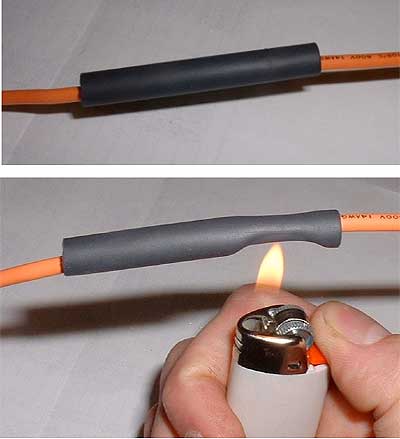
- Next, solder longer jumper wires for the Piezo buzzer just like we did with the LED in step 8.
- Now, add heat-shrink-tubing to protect the wires' metallic joints(do this for the LED and the Piezo buzzer).
- FYI(For your information): Use a soldering iron's heat to shorten the heat shrink tubing!
- Now, get a ruler and find the center directly above the Wall socket(on the Wall socket's side).
- After finding the middle, find the right size drill bit that fits the LED and starting drilling!
- Stick the Led from the inside of the box until you can see the head of the LED start to bulge out of the hole(from the outside)(Look at pictures)
- Apply a little hot glue on the LED from the inside of the box.
- Now get a drill bit that fits perfectly inside the piezo buzzer's hole.
- Using the same drill bit, drill a hole in the middle of a side of the box(For me, I am putting the buzzer on the white line. Check Picture)
- Finally, slide a heat shrink tubing on the GND jumper wire of the LED leg. Then, solder the pins to the appropriate locations. After that, use a soldering iron to shrink the heat-shrink-tubing on the conductive metallic joint(Look at pictures).
- LED's (-) goes to buzzer's(-). And LED's (+) goes to Arduino's pin D11
- Don't do what I did in the 4th picture from the end. Just flip the negative and positive wires, but the Schematic still holds true. SO buzzer's (-) goes to LED's(-). And the buzzer's(+) goes to Arduino's pin D6
- Both LED's (-) and buzzer's(-) are joined with one wire that connects to the Arduino's GND.
- Connect the Relay module to the Arduino. Pin D8 of Arduino connects to IN(SIGNAL) of relay module. And VCC-->5v, and GND-->GND.
- Make sure HC-05's RX(through Voltage divider) goes to Arduino's TX(D1). And HC-05's TX goes to Arduino's RX(D0).
Step 12: Your Status and Uploading the Code


Alright guys,
just unzip the zip file and upload the code from the bottom. Don't forget to include the Time Library .(To see how to add libraries, check out this tutorial)
Now, click upload, and sit back and relax as your Arduino receives HEX files streamed via Bluetooth.
Finally, download the following app from Google PlayStore- "Arduino Bluetooth Controller" by Giumig Apps.
IMPORTANT******If you want to upload again, make sure the Serial Monitor is closed before hitting upload***
So far you have learned how to program wirelessly and cram all things known to man, that gives one an electric shock, in a small box. Well, I say you have come quite far(look at pictures).
The "Final Countdown Timer" code is below:
- If you want more space to run the code on the Arduino, you can comment/delete out the Intro that is located in the Setup(). It starts with "Welcome to Nathan^2's Universal AC Switch..."
- You need to download the code at the bottom, which is in a zip file, in order to get access to pitches.h and the AC_Switch_With_No_Delay code together, or else you will get an error in the code for missing the pitches.h file.
- The code below is just to show what it looks like if you don't have the Arduino IDE Editor.
Attachments
Step 13: Conclusion: Tips and Tricks With Complete Manual
- The first step is open your Bluetooth devices and find your device.(Remember, your password was set when we were in AT Command mode-mine was 1234) "The Default password is 1234"
- Second, open the Arduino Bluetooth Controller App.
- Third, click on your device and make sure no other device is connected to it. Also, make sure the Arduino is plugged in via DC jack or USB.
- FYI: The USB port is unavailable because the Bluetooth module has turned your Arduino into a wireless receiver, so you can't program via USB, but you can power it via USB and then program wirelessly(As if you were programming via USB, but you are not).
- Click on Terminal Mode.
In the beginning, "The Final Countdown" timer will ask you how long you want to turn on your machine.
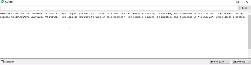
- The annoying thing is that when you plug in your Arduino with power, the Serial spits out the Intro paragraph(which can be deleted in the Setup()).
- The Serial repeats Setup() every time a new device connects
- So every time you enter the program via Bluetooth after plugging in the Arduino's power, you will be given the Intro paragraph twice!
- To avoid this, enter terminal mode twice(just exit out of the program and click on your Bluetooth device again). You only have to do this once every time you give the Arduino power.
- This unavoidable bug happens only for the first time when your phone connects to the Arduino.
- There are no consequences if you enter terminal mode once or twice(It's just less annoying).

***************************************************************************************************************************** Complete Manual
- Timer commands
- If you wanted a timer for 1 hour and 29minutes and 30s, you would type '1h29m30s' and the order doesn't matter. And if you really wanted to mess around you could say ' 29am 1 wh 3q,0wes ' and still get the same result; as long as the number of hours/minutes/seconds is always before the letter that stands for the unit of time, it is a valid keystroke. Except for the letters 'y' and 'v', since they have the potential to activate when the timer hasn't started yet(look below).
- Let's say we want a Ninja smoothie maker to run for 1 minute and 30seconds
- We would type in '1m30s'
- If you don't type anything after your input, the Arduino will assume you are confused and will give you a hint. For example "Hint: Type 'v' to view timer." means when you type 'v' the Arduino will talk back to you and tell you how much time you have entered. It's kind of like an Advertisement. These are just one of the benefits to multitasking.
- These commands only work when the Timer hasn't started(for safety reasons)
- How to view timer?
- Type 'v' //You don't have to type v to start the timer; it just ensures you if what you typed is correct or not.
- How to start the timer?
- Type 'y' for yes.
- A beep will follow after you start, and the LED will start to fade at a faster rate.
- Type 'y' for yes.
- How to view timer?
- These commands only work after the timer has started(for safety reasons, such as someone's baby clicking 'y' too many times on your phone and sets the timer for infinite(or greater than 50 days :] ))
- How to pause/resume timer?
- Type 'p' //spits out the time a pauses timer
- How to reset the Timer?
- Type 'r'
- How to end the Timer?
- Type 'e'
- How to watch the amount of Time Remaining?
- Type 'w' //spits out the time and does nothing else
- How to pause/resume timer?
- These commands work at all times(Because it's safe either way)
- How to turn off Buzzer(Sound)?
- Type 'b'
- How to toggle the Light? //Say you don't like the light because it's too bright. Well, you can turn it off and the timer will still do its job! Isn't multitasking beautiful!
- Type 'l' to toggle light from Off->On->Fading
- When paused, the LED will blink every second.When resuming, the LED will continue at its normal faster rate.
- Tricks
- Let's say you wanted a time of "1m40s" but you accidentally typed "1m0s". Well, it is quite simple to fix. All you do is type "40s". Then, when you type 'v' to view your timer, you will see the Arduino say 1 minute and 40 seconds.
- Combos:
- Say you are too lazy with talking with your Arduino friend and you just want to get the timer started. Well, now you can cut Arduino off.
- Say you just want to cook that salmon for 1 hour, 20 minutes, and 5 seconds. All you have to type is "1h20m5svy"
- Say you are too lazy with talking with your Arduino friend and you just want to get the timer started. Well, now you can cut Arduino off.
- You probably noticed that you can't type a time above 1 hour and 30 minutes. This is because I wanted to add a safety feature to this product.
- Ex: Say someone's baby accidentally types in '100h'. This would last 100 hours which probably wouldn't be good for the machine and your electrical bill!
- If you want to change this limitation, go to the "Final Countdown" Timer Code and type CTRL+F. Now search for 'maxLoad'. Now, above maxLoad you will notice three int variables.
- Right now, the max run time is 1 hour and 30 minutes.
- But if you want a maximum run time of 4 hours, you would say:
- int hr=4;
- int mn=0;
- int sec=0;
- How to turn off Buzzer(Sound)?
- We would type in '1m30s'

Step 14: Epilogue: Explaining the Code
I highly suggest listening to the video.
I will explain the main complex code because everything other than the Pause/Resume code is easy to learn on your own. So the Pause/Resume Code will be explained in the video more than anything else. If you guys want an extra interpretation of the other parts of my code, please don't hesitate to ask through the comments.
If you need extra help with the FadeWithoutDelay check out the Bald Engineer's website.
The MelodyWithoutDelay was invented by me. It is basically the same thing as toneMelody, except it doesn't contain delay. Check out my original code for MelodyWithoutDelay below:
- This song is the same as the "FINAL Countdown", but it is the extended version which lasts for 41 seconds.
- To activate, type 'g'. To test the Arduino's multitasking capabilities type 'h' and the Arduino will say "hello" to you while singing a tune!
- You can upload the code below to the "Final Countdown" Timer box; nothing bad will happen.
===================================================================================
I hope you guys enjoyed this tutorial and I hope that a majority of you will be able to program wirelessly!
Do you want to create an instructable? Check out this link to get enrolled in a free class to help jump-start your interest in Instructables.
The point is to have fun out there and make something that you and others find interesting, which is the hard part, and then you must explain each step in critical detail. I hope you will join our Instructables community!
And remember, try to use less delay in your code and during your job, of course :)
Attachments

Runner Up in the
Microcontroller Contest 2017


