

Introduction: Thermostat Control of a Heat Exchange Fan


Hi Everyone,
In this Instructable, I’ll show you how to automate a heat exchange fan using a cheap thermostat module.
Warning: This project uses mains voltage and needs to be properly handled. I’ve you are not sure what are you doing, do not attempt to replicate it.
Step 1: Project Background


My entire home is being heated with a pellets burning boiler that sits in my basement. On top of it, where the chimney attachment is I’ve installed a heat exchanger so I can trap some of the heat going outside and heat the basement.
The exchanger works perfectly but I’ve been turning it on and off manually each time I start and stop the boiler and I wanted to automate this task.
Step 2: Theory of Operation


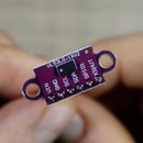
As a control board, I’ve bought this thermostat module for several dollars on the Internet that can be setup for working with both cooling and heating control. The module uses a 10k NTC probe to sample the temperature and it is then compared with a given threshold.
As soon as that threshold is passed, the relay switches on and it stays that way until the temperature is below the threshold.
Step 3: Disassemble


The exchanger fan is originally controlled with a dimmer switch in order to regulate the speed at which it turns, so I started the project by first removing the cable and the regulator from the fan.
At my desk, I opened the regulator case and removed the cable completely so it can be re-routed through the relay on the thermostat.
Step 4: Connect the Thermostat


To power the entire assembly I’ve taken out the board from 9V power supply and connected it directly to the thermostat. On one side of the relay contacts I’ve connected the live wire coming from the wall socket and the other contact is then connected to the speed controller for the fan.
The entire schematic is very simple but you need to be very careful not to mix up the wires from the high voltage side to the low voltage side as that will be catastrophic for the electronics.
Click on the link bellow for the full schematic:
https://easyeda.com/bkolicoski/Automted-Thermostat...
Once all of the connections were made, I made sure to test it before I continued with putting everything into an enclosure.
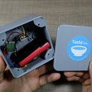
Step 5: Prepare an Enclosure


For the enclosure, I’ve used a junction box to house everything in. Based on your requirements you may choose to add holes or windows to it so you can monitor the temperature or adjust the speed from outside of the box but I had no need for that. Instead I’ve isolated all of the modules to prevent any shorting inside and stuffed everything in.
Step 6: Mount the Thermostat


The control box is then mounted with zip ties to the boiler and I made sure to choose a place where there was no heat coming out as that can damage the electronics. This bar from where the pump control lines already come out was the perfect choice.
After the box was mounted, I’ve used an aluminium sticky tape to glue the NTC probe to the exhausts pulling fan on the back as this is the first part that heats up when the burning starts and cools off once it stops.
Last, I’ve connected back the wires to the fan and started the boiler to test the entire assembly. As expected, everything run perfectly so I could declare this project as done.
Step 7: Enjoy!
I hope that you liked this Instructable so follow me here and subscribe to my YouTube channel so you don’t miss future projects where we explore the world of electronics and code.
Cheers and thanks for reading.


