

Introduction: Upside Up - Robot Balancing Revisited


This instructable walks you through building a simple, 2 wheeled balancing robot, and spends some time exploring the various factors influencing balancing performance. This is my second robot project, and I had two key motivations–to determine, and improve on, the factors limiting the first robot’s balancing performance, and to incorporate the more integrated Arduino 101 form factor. If interested, here is a link to the instructable for my first balancing robot project.
The key components of this robot include the Arduino 101 board, an Arduino motor control shield, two 12V geared DC motors with encoders and a Bluetooth module. Finally, an inexpensive battery allows the robot greater mobility and a companion Android app enables robot tuning and control. Here are a few links to more ingredient specifics:
- Arduino : Arduino 101 - $30.00
- Motor Control : Keyestudio Shield L298A - $6.50
- 2x DC motors : 12V 29:1 geared motor with 64 CPR encoder - $23.00 ea
- Bluetooth : KEDSOM Arduino Wireless Bluetooth Transceiver Module - $9.99
- 2x 1600mAh NiMH Batteries : Duratrax NiMH 6.0V 1600mHa Flat Rx Univ Connector, ONYX110 Battery Charger – battery $15.00 ea, charger $25.00
Going into this project, I had a few ideas on how to improve the balancing of the robot:
- Control loop time interval – The first project used a 20mS loop for the balancing PID. Maybe this needed to be faster for better balancing?
- Sensor fusion filter – The first project used a canned Kalman filter with no ability to control filter attributes. Maybe the the filter wasn’t responsive enough or was too noisy?
- The use of positional feedback (encoders) – Was distance and/or speed feedback necessary for better balance control?
- Control loop variables and structure – Would changes in the IMU sensors used, or the PID structure or implementation help improve balancing?
In the end, I was able to achieve noticeable improvements in balancing performance, and I must say I was a bit surprised at what changes provided the biggest improvements!
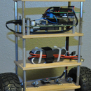
Step 1: Chassis


The robot chassis follows a fairly common tiered design, using readily available material - ¼ inch plywood for each tier, and standoffs to connect the tiers.
Robot assembly started with the motor tier, using the dimensions shown in the diagram. Using a 1/4" bit and an edge guide on the router router, 8 slots were cut to mount the DC motors, and a 9th slot was cut for the motor control wires. This last slot was sized to allow the motor wire connectors to fit through the hole. The mounting holes were drilled in each corner, and counter sunk on the bottom so that the mounting screw heads would be flush. The motors are attached to the ¼ plywood tier using hose clamps. To allow for a flexible, but robust motor electrical connection, a 90 deg through hole connector was used, fastened to the motor tier with a custom bracket.
The Battery tier is similar, but with only 2 slots for the battery Velcro strap. It includes the same corner mounting holes, but additionally two larger holes were drilled to route the motor wires up to the electronics tier. To avoid induced noise, the power and control wires are routed on separate posts. The two batteries are zip tied together, and fastened to the plywood with a Velcro strap found at a local hobby store.
The Electronics tier preparation involved drilling the same mounting and wire management holes, as well as the mounting holes for the Arduino board complex and the power switch module. The top tier contains only the 4 corner mounting holes. I completed the chassis by designing dampeners for each corner, with built in plastic springs and felt pads, intended to soften the impact of a fall. It turns out, falls are an integral part of developing a balancing robot.
For the final step of construction, I used RC truck tires on the robot. I purchased a set from a local hobby store, but they are similar to these online. The axle-to-wheel adapter design uses a 10-32 set screw to hold the adapter to the motor shaft. A slot for a 10-32 nut is included, allowing the wheel to be directly attached and a metal tap bit was used to add the threads to the set screw hole after the adapter was printed. .
Below are the STL files for the 3D printed parts. I used Autodesk Fusion 360 for design, Cura for slicing and then printed them using PLA on a Simple Metal from PrintrBot. The only tricky one was the bumper, where I needed to use 0.4mm for the shell thickness to get the desired result.
3D Printed Parts:
- Motor Tier Connector Bracket :
- Arduino 101/BT Bracket:
- Power Connector/Switch Module:
- Motor Shaft-to-Wheel Adapter:
- Bumpers (right, left):


Step 2: Wiring


The wiring connections between the robot electrical subsystems are shown in the wiring schematic diagram.
To connect the motors to the motor shield, I used 20 gauge stranded wire for power, and CAT 5 solid wire for encoder connections. I made extensive use of single-post connectors and heat shrink, for robust but flexible connections.
I chose the Keyestudio motor shield because it was inexpensive and it had a small proto area. A 4x1 single row header was used for connectors to the Bluetooth module and motor A and B encoders. I also put the voltage divider, to convert from the 12V of the battery to 3.3V of the Arduino 101 analog input, on the motor shield. For connections between the resisters, headers and Arduino pins, individual wires from the CAT 5 cable were used.
Note: I don’t know if there was an error manufacturing my board, or if they were meant to be shipped this way, but I had to short the V-logic to 3.3V on the motor shield with the pads provided on the board. The pads were empty as delivered, and this connection needed to be made for the motor shield to work.
There is a mismatch between the motor shield and Arduino 101 on the pin assignment of PWMB, the pulse width modulation control for motor B. The shield has this on pin D11, but Arduino 101 does not support PWM on D11. To work around this, I assigned PWMB to D9 in the Arduino 101 sketch, and added a jumper on the motor shield between D9 and D11. As an additional precaution, I clipped the D11 pin on the motor shield to avoid any possible contention between D9 and D11 on Arduino 101.
A power jack input was included so that the robot can be operated with corded power. I used this extensively in early testing, as no battery charging is required, and you get a consistent supply voltage.
Note: When tethered, I used a 12V/5A power brick as a power source, which is NOT intended to charge a battery. Either a power brick OR a battery can be used as the power source for the robot, but NEVER both at the same time. The battery must be charged with an appropriate charger.
Step 3: Software
I divided the robot sketch into 4 files, primarily to aid in code readability. The files, and general content are:
- SimpleRobot.h: Header file containing #defines, class definitions and function prototypes
- SimpleRobot.cpp: C++ file containing PID and motor control class functions.
- Bluetooth.ino: Code implementing Bluetooth communication with the Android App.
- SRG2_Bal_Final.ino: Main sketch for the robot.
The code does reference Arduino.h, CurieIMU.h and MadgwickAHRS.h, so you will need to have installed the necessary libraries for Arduino 101 for it to compile.
I won’t go through a full code walk through, as the code is fairly well commented, but will make a few general comments:
- The sketch uses both a Madgwick and Complementary filter for sensor fusion for performance comparisons – yaw comes from Madgwick, and pitch comes from the Complementary filter.
- Encoder information is logged using an ISR (interrupt service routine) separately for each motor. Robot speed uses an average of the two, so a spinning robot will register near 0 speed.
- A simple data logging implementation is included, although the limited Arduino 101 memory results in a pretty small data set. Data capture is started through an instruction from the Android app, and the data capture interval is controlled through a #define statement. The header and data to be captured are defined at the bottom of the main sketch. Data is automatically transferred to the Android device and saved in CSV format, once capture is complete.
- The Bluetooth module to Arduino 101 communication frequency is set pretty high (921600) to reduce the overhead/latency of communication over this interface. Depending on the signal integrity of a specific implementation, this may need to be reduced.
- Initially I was unable to download sketches to the Arduino 101 due to USB driver issues. In the end I had to buy and install a USB3 add-in card in my host PC to get it to work. They have since released more updated SW, so this issue may be addressed, but I have not confirmed it on my setup.

Step 4: Android App

To allow real time adjustment of the robot control parameters and monitoring of telemetry data, I developed a companion Android App. It was developed using MIT App Inventor 2, which has a volume of educational and training information available.
The app is a simple collection of buttons and sliders to allow the user to configure and control the robot. Above is screen shot of the application – its use is pretty self-explanatory. A few notes:
- Speed and Direction are very rudimentary and the set of button above those sliders have no effect, as full navigation control is not implemented in this version of the robot.
- Every time the app is started, or the robot power cycled, the user will need to connect to the robot BT module using the button provided.
- The Standby button is used to take the robot into balancing mode, and the same button will return the robot to standby. When active, a timer replaces the text in this button.
- The Edit PID button will enable the P, I and D “+” and “-“ buttons, allowing modification of the PID multiplier values.
- A data log sequence is started when the Datalog button is pressed. The button text color will change from gray to black during data collection and from black to orange when data is being transferred from the robot to the Android device, and back to black once the transfer is complete. Due to the overhead of using MIT AI2, the Android device tends to be pretty sluggish during this data transfer. The file will be saved as SimpleRobot.csv. Googles Fusion Table proved to be a good method of visualizing the data.
I have included the aia file so you can open it in the MIT App Inventor environment to further study or modify the Android App.
Attachments
Step 5: Balance Optimization


And now we get to the interesting part – how to improve the robot's balancing performance. I had some ideas on where to start looking, but as with any system, it is hard to know what the variables cross dependencies are. So rather than get too analytical, I just jumped in.
Control loop time interval
I started by varying the time interval at which the balancing PID was evaluated. I measured the default Arduino 101 PWM period at 2mS, and my previous project had used a value of 20mS so I started at 5mS and doubled the interval until the robot couldn’t balance. At 5mS, the robot was able to balance, but it seemed to be overly active, and oscillated with a period of roughly 120mS. At 10mS, it was again able to balance, but the oscillations slowed down to 280mS. At 20mS, the oscillating period picked back up to roughly 180mS, but rather than active, the response seemed sluggish. At 40mS the response became even more sluggish, the balancing erratic, and the robot was not always able to stay balanced. My conclusion was that while the PID evaluation interval can certainly influence the robot behavior, and indeed had to be above some minimal rate to be able to balance, it was not the magic bullet. For the rest of my testing I used a 5mS control loop interval.
Sensor fusion filter
Next I moved to the sensor fusion filter. Why do we need a fusion filter anyway? To answer that question, we need to examine the heart of a balancing system, the IMU (Inertial Measurement Unit). An IMU consists of two types of sensors – a gyroscope and an accelerometer. The gyroscope measures the angular rate of change, or angular velocity. Theoretically a good estimate of angular position can be generated by integrating the output of the gyroscope. Unfortunately, gyroscope sensors have an effect called drift – that is they will register some small angular velocity even when sitting dead still. So if you generate your estimated angle only by integrating the gyroscope output, you would have an error that would continue to grow over time – a problem that makes a gyroscope only solution untenable for balancing. Enter the accelerometer. The value reported by the accelerometer will include the effect of gravity, which is constant, as well as any other acceleration, which will vary based on device movement. For the IMU, it is the gravity vector we are interested in. The idea of a fusion filter is to generate an estimated angle by combining these two sensors. It favors the gyroscope output instantaneously (passed through a high pass filter) but the accelerometer output over the long term by measuring earth’s gravitational direction (passed through a low pass filter) to remove any drift.
Ok, so we need a fusion filter, but which one? Very complete, and complex solutions exist. The Kalman filter is one of the more prominent fusion filters, but even an engineering degree may not fully equip you to understand what is in the black box. For this project I used a similar, but less computationally demanding solution, the Madgwick filter. I used this filter for one main reason – it came bundled with the Arduino 101! But the configuration of the IMU in the balancing case – only one degree of freedom, creates constraints that allow us to use a more simple solution, the Complementary filter. The Complementary filter gets its name because the multiplying factors for each term add up to 1. A block diagram of a complementary filter is shown in Figure 1.
There are some very good treatments on the web for the details behind the complementary filter, so above I have just provide the resulting filter equation. In the equation, A is a constant that determines the filter characteristics. In addition, it should be noted that in the accelerometer angle calculations, we are taking advantage of small angle approximation – a realization that for angles less than ~30̊, sin(θ) ≈ θ in radians. For our robot, if the angle approaches 30̊, it is going to fall over, so that assumption seems valid. As a result we can skip the sin(θ) in this calculation with little impact. Finally, the time constant for the complementary filter is also shown above.
I tested both the Madgwick and Complementary filter to see how it impacted the balancing of the robot. The stock Madgwick filter as installed had the Beta set to 0.1, using a #define statement in the MadgwickAHRS.h header file. The robot would not balance with that setting – the response was a bit too sluggish. After playing around, I found a setting of 0.01 enabled the best balancing, though there was some compromise in absolute angle accuracy with that setting. If you held the robot at an angle for a moment, say 20̊, and then returned it to upright, there was a lag in the estimated angle returning to 0̊.
For the complementary filter, I used A = 0.98, which gives a time constant of about 0.25 seconds, with dt set to 5 milliseconds. I found the results to be comparable to the Madgwick filter, and better than my first project, but still not rock solid balancing. So the search continued.
The use of positional feedback (encoders)
The geared DC motors I selected for this robot included encoders to provide feedback on the movement of the armature of the motor. The encoders are on the motor shaft before the gearing occurs, so they provide a pretty high resolution on movement - with the gear ratio and diameter wheels used, I determined that each encoder transition translated to ~0.04cm. Distance and speed were then pretty straightforward to derive, by counting encoder transitions over a regular time interval, and then multiplying the result by 0.04 to get distance, and dividing that distance by the time interval (20mS in my case) to get speed.
I am planning my next project to tackle more fully the navigation capabilities of the robot, so I won’t go into much detail here, but two methods were used to control the speed of the robot – setting the target angle and direct addition to the motor PWM values. Adding speed control did remove the robot “wandering” but did not significantly improve balancing. On to the control loop.
Control loop variables and structure
The main control loop for the balancing robot is based on two elements – the fusion filter to determine the estimated angle of the robot and a PID controller to use the estimated angle to generate the motor control signal. The idea behind a PID controller is to calculate the error of a control signal against a set point, and then sum the proportional, integral and derivative forms of that error after they have each been multiplied by separate constants. The PID controller very versatile as a control element, with access to where the error has been (I), where it is now (P) and where it is headed (D). But be forewarned - it can be a very challenging task to optimize the multipliers for the P, I and D terms. Figure 2 is a block diagram showing the basic structure and control connectivity, and reflects the initial configuration of this robot.
Upon closer inspection, you may notice that the PID controller D term is taking the derivative of the estimated angle, which results in an estimated angular rate of change. If you remember, the gyroscope was providing just that, an angular rate of change, but one that is much more accurate. This leads one to wonder how the control loop would behave if the gyroscope output were used directly, rather than recalculating angular rate from the estimated angle.
After feeding the gyroscope directly in the D term of the PID, the change in balancing performance was dramatic. Figure 3 gives a glimpse at why – it shows the gyroscope output alongside the D term of the PID. The angular rate of change derived from the estimated angle lags the gyroscope output by over 150mS, a delay which helps explain some of the wobble in the balancing of the original configuration, and makes you wonder how it balanced at all.
Figure 4 shows the final configuration, with the gyroscope being fed directly into the D term of the PID controller. While all of the areas explored had some impact on balancing performance, providing a timelier and higher fidelity indication of angular rate from the gyroscope provided the change in robot performance I was looking for.
Step 6: Conclusion

In the end, I found some pretty significant improvements in the balancing performance of the robot. I am sure there are more to be had, but the platform balances well enough to move to the next phase of the project – adding better speed and direction control for navigation.
All of the areas investigated had some impact on balancing performance, but I would rank them as follows, from highest impact to lowest:
- Control loop variables and structure – Using gyroscope output directly in PID D term. What a difference!
- Sensor fusion filter – Both Madgwick and Complementary filters worked well. Whichever filter is used needs to provide adequate response time.
- Control loop time interval – Anything under 20mS worked, though the shorter time intervals were a bit more stable.
- The use of positional feedback (encoders) – held robot more stationary, not a huge impact on balancing.
I was impressed with the compact size of the Arduino 101, and have enjoyed using it in this project. While it does include Bluetooth LE support, the work necessary to use it as a control port was more than this project warranted, so I went with a simpler solution based on an external Bluetooth module.
That does it for this simple robot project. Now it is time to make your own. Enjoy!


![Tim's Mechanical Spider Leg [LU9685-20CU]](https://content.instructables.com/FFB/5R4I/LVKZ6G6R/FFB5R4ILVKZ6G6R.png?auto=webp&crop=1.2%3A1&frame=1&width=306)


