

Introduction: Variable Voltage Supply


Its a simple and handy 'LM317 voltage regulator' based variable voltage supply. Along with some capacitors and resistors.
Step 1: Materials Required


Electrical components:-
1. LM317 voltage regulator
2. Variable resistor (10k ohm in my case)
3. R2 resistance (R2 value in step 2)
4. 1 uF capacitor
5. 0.1 uF capacitor
6. Power supply less than 40 volts
7. Led (optional)
8. 1k ohm resistor for LED
9. Screw terminal
10. Heat sink
11. Perfboard or PCB
Tools:-
1. Soldering accessories
2. Hot glue gun
3. Insulation tape
4. Cutter and stripper
5. Multimeter
6. Screwdriver set
Step 2: Calculating Value of 'R2'

You can easily find out the value of resistance of R2 in ohms by using the formula given in the above image. Put value of variable resistance (in ohms) in 'R1' and the voltage given by your power source in the 'Supply voltage'.
example: If you use a 12V lead acid battery then 'Supply voltage' = 12
If you use variable resistor of value 10k then 'R1' = 10000
Step 3: Circuit Diagram


Here with the help of this diagram you can put the components accordingly. Make sure you will connect the pins of LM317 in correct manner ,according to the circuit diagram. I told this thing because the pins given in the diagram are in opposite order with respect to LM317 actual pins. I recommend to first build the circuit on breadboard for testing purposes. I had not taken stepwise pictures of the circuitary and other steps (forgot to do so :P), but I think anyone can built this circuit with the help of diagram easily because its a very simple and basic circuit. The capacitors used here help in giving out a steady voltage, without including them it may be possible that the voltage fluctuate. Also attach a Heat sink on the LM317 in order to let the heat dissipate. Heat produced is directly proportional to the difference in input and output voltage. If you want to attach a LED indicator in the circuit, simply connect that in the output terminals along with a suitable resistor (10k ohm will work fine) also it gets dimmer as the voltage drops. For more information on LM317 go through datasheet I had attached.

Step 4: Finalising

Once the circuit works fine on checking it with a multimeter solder all the components on a perfboard or PCB. I had connected a two pin screw terminal on the output. I am thinking to make a custom enclosure for it so that the components are not visible. Now its ready to use.
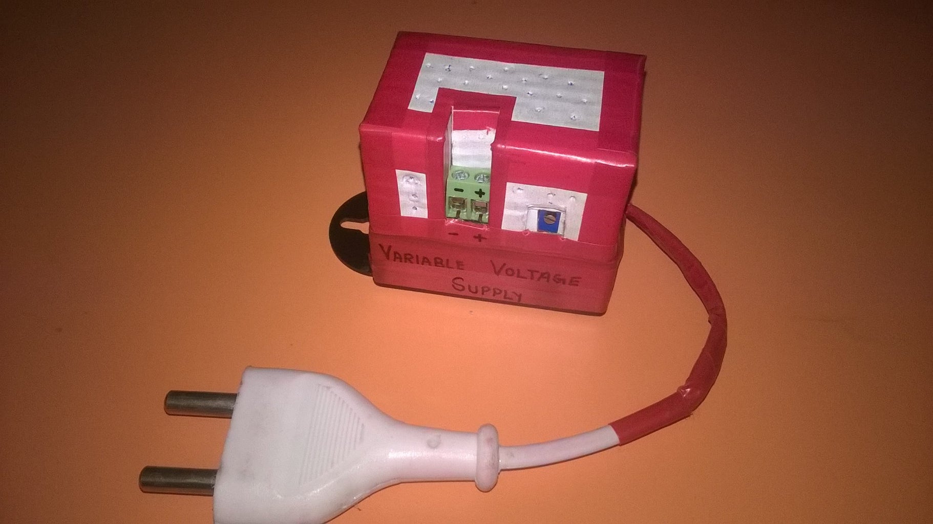
Step 5: Upgrade


In meanwhile time I had made a enclosure for the supply (yea I have a lot of time to waste :p). Also I had replaced Rotary potentiometer with rectangular pot (small one) so that the voltage will not vary until I rotate it with screwdriver, but the main reason for replacing it is due to its precision i.e. on rotating the screw of this smaller pot, it changes voltage at a slower rate than the rate of the bigger pot. Also it is very compact. This time I have also shown the pics of maximum and minimum voltages of the supply, when used a 12 V supply as input (my case).

![Tim's Mechanical Spider Leg [LU9685-20CU]](https://content.instructables.com/FFB/5R4I/LVKZ6G6R/FFB5R4ILVKZ6G6R.png?auto=webp&crop=1.2%3A1&frame=1&width=306)


