

Introduction: Vintage Intercom Re-purposing


I bought a beautiful old intercom in the local car boot sale and thought it would be good to use it as the door intercom for our "stair" (as Victorian apartment blocks are called in Edinburgh).
It's a GEC K7867 and looks looks pre First World War. Our local museum has an almost identical model from 1904. But, in fact, this one is early 1930s - GEC went on making them for 30 years.
It's an intercom (rather than a public telephone) and was part of a system with 5 stations.
The way it worked was: you turn the knob at the top to point at one of the other station numbers, lift the earphone then press the "call" button. The bell at the other station rings and a latching mechanism locks you into not receiving other calls. When you've finished, you replace the earphone and the mechanism unlatches.
So it contains all the parts needed for a door intercom: a microphone, a speaker, a bell and a button. Any similar telephone-like object can work as a door intercom.
As it's a somewhat historical object, I only made changes to it that could easily be undone.
This Instructable gives general principles that could be applied to other door intercom conversions. It also shows how to replace a carbon microphone of an old telephone with a modern electret microphone.
You'll need the usual handtools and a soldering iron; plus a few electronic components it you have to replace the microphone or internal switches.
Step 1: The Current Intercom


The current intercom was installed in the 1980s and is rather ugly. The circuit is very simple but it has worked reliably for over 30 years.
The handset unit contains:
- a carbon microphone
- a speaker
- a hook switch
- a buzzer
- a lock button
It's a typical design for door intercoms. The microphones, speakers and buttons are wired in parallel for all the flats. Each flat has its own buzzer wire so only one buzzer sounds when a visitor presses a button.
Make a note of how yours is wired up and the colours used.
Many door intercoms are constructed that way. Some modern ones just have two wires and all the cleverness is done with digital electronics. If your intercom is like that, there will be a circuit board inside the handset station. You'll need to port it into the new intercom you're building.
Step 2: The Old Microphone

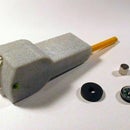
The old microphone of the K7867 was broken. As you can see from the photo, the brass mouthpiece had been squashed and that had shattered the diaphragm.
A carbon microphone works with a chamber filled with powdered carbon. a separate diaphragm is mechanically coupled to the chamber and the changes in pressure due to sounds change the resistance through the carbon.
A DC voltage (5V to 7V) is applied to the chamber. The changing resistance changes the current drawn from the supply.
Early carbon microphones like this one used the diaphragm itself as the lid of the chamber. The diaphragm is made of some sort of carbon and is very brittle. That's what had broken.
Carbon microphones were never very good quality and when you restore an old telephone it's usual to replace the carbon microphone with a modern electret microphone.
Step 3: The New Microphone


The modern intercom also used a carbon microphone. That seems a bit old fashioned nowadays but probably made sense in the 1980s. It is powered from a 7V source.
You can tell that your intercom has carbon microphone if the microphone is big and its resistance is exactly the same in both directions (i.e. swap the leads round on your multimeter). A typical electret microphone is much smaller: 9mm dia and 6mm high. Look on the web at pictures of electret and carbon microphones if you're not sure what you've got.
All the replacement carbon microphones I could find were too big to fit in the microphone housing of the K7867 so I was forced to use an electret microphone.
The output from an electret microphone is much smaller than from a carbon microphone - maybe less than a tenth - so it needs amplification.
You can buy electret microphone replacements for old telephone microphones. They include amplification but they're huge - they're meant to be drop-in replacements. So I had to build my own circuit.
As the only circuit I could find on the web didn't work, I designed my own. It uses pretty well any small signal NPN transistor and a few other components that you've probably got in your junk box. (If you have to buy a transistor then ask for a 2N2222 or a BC109. The 10uF capacitor should have a voltage rating at least twice the 7V supply. If you take apart any scrap electronics from the 20th century, you'll find most of the components you need.)
An electronics expert might look at my circuit and say that as the output from the the transistor varies, there will be negative feedback through the 10k and thus the amplification will be reduced. True. But the circuit works well. If you're really worried, you could RC decouple the supply to the microphone.
The way you build the circuit will depend on the size and shape of your microphone housing. I needed mine to be low height. So I used stripboard but soldered all the components on the copper side so it was rather like making a surface-mount circuit. That way, the insulation side was completely flat and could rest on the metal microphone housing.
If you need help using stripboard, there's an instructable here.
Step 4: The Earphone

The old earphone works well. That's often the case with old telephones (unlike their microphone). It's a little quieter than the 1980s intercom speaker but perfectly adequate.
Step 5: The Lock Button and the Bell

The modern intercom has a pushbutton you press to operate the solenoid at the street door lock and let the visitor in. One side of the solenoid is connected to 12V AC and the button connects the other side to 0V.
The "call" button of the K7867 works fine for that function but I added a layer of insulation so the button is not connected to any intercom voltage. The intercom is electrically isolated via a transformer but it's good practice not to let the user touch metal parts that might become live if, say, the transformer develops a fault.
The modern intercom uses a buzzer driven by 12V AC which sounds when a visitor presses a button at the street door.
The K7867 has a bell that is meant to run on 6V DC but needed a little adjustment. Even then it didn't work well. It preferred 12V and worked fine with 12V AC. Perhaps I should add a few ohms resistance to limit the current.
The contacts sparked more that I liked so I added a 100nF capacitor across them.
Step 6: The Hook Switch


The K7867 contains a hook switch but the connections are not quite right for what's needed.
I moved the contacts out of the way with with wooden blocks then added two lever-microswitches to act as the DPST switch that's needed. You can see the microswitches in the top-left of the box. A stiff but slightly springy wire connects them to the hook lever.
The latching mechanism that's operated by the hook was removed.
Step 7: The Circuit


The overall circuit didn't need many changes - just a couple of wires disconnected and a few soldered on. All the changes are easily reversed.
It's simply a matter of studying the circuit and working out the similarities and differences between the two intercoms.
I'm sorry I can't give precise instructions on how to convert an old intercom that you've found. The details will be different but the general principles will be the same.
A webpage describing this project is here. It has links to some my other projects.


