

Introduction: WiFi Bathroom Humidity Sensor W/Fan Control, App & Automation


If your like me you always forget to turn on the bathroom fan. In this project I solved my bathroom humidity problem by automating the fan. I used a humidity sensor, wemos d1 mini, relay and the Blynk app.
Subscribe for great videos: http://YouTube.com/Innovativetom
WEMOS, Arduino and Blynk:
https://github.com/esp8266/Arduino.git
Used (using the links below help me build more projects, even if you don’t buy the linked item and by something else I still get a little something. THANKS! ):
Wemos Kit (everything you will need and PRIME!) - http://amzn.to/2p0rRFb
Wemos D1 Mini - http://amzn.to/2p0o7DR
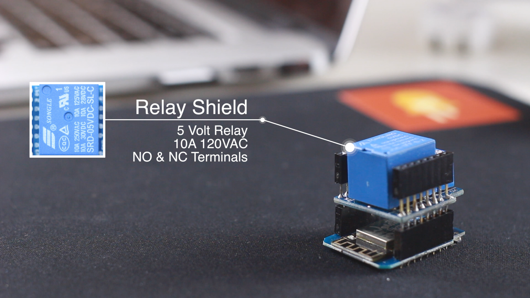
Wemos Relay Shield - http://amzn.to/2oqPovN
Wemos Temp & Humidity Shield (DHT22) - http://amzn.to/2oaCQaa
Wemos Temp & Humidity Shield (DHT11) - http://amzn.to/2p0mwOa
Power Cord (to cut) - http://amzn.to/2wbHudI
Zip tie Blocks - http://amzn.to/2xmjTHw
Zip ties - http://amzn.to/2izlfeN
Micro USB Cable 3' - http://amzn.to/2p0m42q
See all my tools at http://innovativetom.com/#tools
In order by most used:
Instagram: https://www.instagram.com/innovativetom/
Twitter: https://twitter.com/innovativetom
Instructables: https://www.instructables.com/member/innovativetom...
Pinterest: https://www.pinterest.com/innovativetom/
My Website: http://innovativetom.com/
Step 1: The Board & Shields


Wemos D1 Mini
11 digital input/output pins, all pins have interrupt/pwm/I2C/one-wire supported(except D0)
1 analog input(3.2V max input) a Micro USB connection
Compatible with Arduino
Compatible with nodemcu
DHT11
Temperature: -20~60°C Humidity: 20-95%RH (±5%RH) It uses D1 and D2 of the WEMOS Board and is extremely popular. They tones of information and code already written for it.
Relay
The relay is a basic 5v relay and can switch up to 15A @ 120V I\
Step 2: Code!

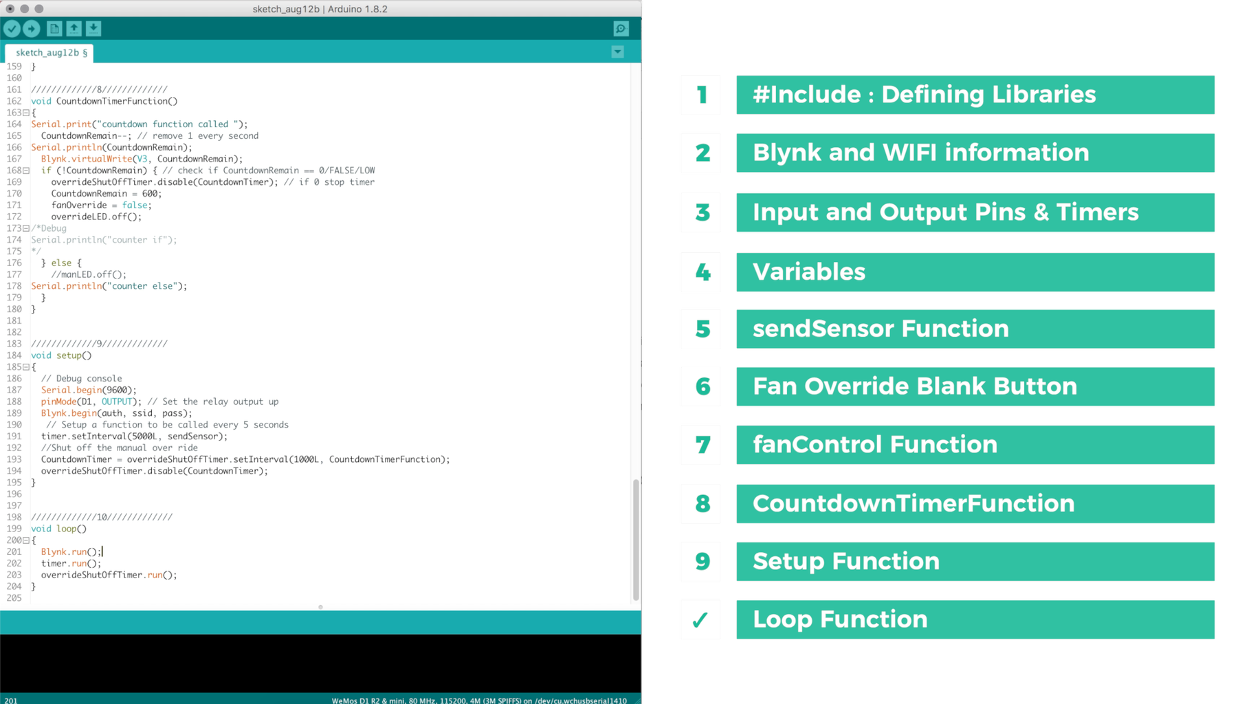

Get the latest version here:
https://github.com/Innovativetom/Automatic-Bathroo...
/*************************************************************
Download latest Blynk library here: https://github.com/blynkkk/blynk-library/releases/latestBlynk is a platform with iOS and Android apps to control Arduino, Raspberry Pi and the likes over the Internet. You can easily build graphic interfaces for all your projects by simply dragging and dropping widgets.
Downloads, docs, tutorials: http://www.blynk.cc Sketch generator: http://examples.blynk.cc Blynk community: http://community.blynk.cc Social networks: https://www.fb.com/blynkapp http://twitter.com/blynk_app
Blynk library is licensed under MIT license This example code is in public domain.
************************************************************* This example runs directly on ESP8266 chip.
Note: This requires ESP8266 support package: https://github.com/esp8266/Arduino
Please be sure to select the right ESP8266 module in the Tools -> Board menu!
Change WiFi ssid, pass, and Blynk auth token to run :) Feel free to apply it to any other example. It's simple! *************************************************************
////////////1////////////
* Comment this out to disable prints and save space */ #define BLYNK_PRINT Serial
#include #include #include #include
/////////////2///////////// // You should get Auth Token in the Blynk App. // Go to the Project Settings (nut icon). char auth[] = "";
// Your WiFi credentials. // Set password to "" for open networks. char ssid[] = ""; char pass[] = "";
/////////////3///////////// // Setting up the pin and DHT version #define DHTTYPE DHT11 // DHT Shield uses DHT 11 #define DHTPIN D4 // DHT Shield uses pin D4 DHT dht(DHTPIN, DHTTYPE);
// Set Colors of LEDs /* Not currently used //Widget Colors #define BLYNK_Green "#23C48E" #define BLYNK_Blue "#04C0F8" #define BLYNK_Red "#D3435C" */ //Set up of the Humiditly LED & override LED //these are software LEDs in app WidgetLED humLED(V1); WidgetLED overrideLED(V2);
//this timer is used for the blynk app/server and to call data from the sensor BlynkTimer timer; //this timer is used to shut off the fan after a cer SimpleTimer overrideShutOffTimer;
/////////////4///////////// //Sensor varables float h = 0; float t = 0;
//Fan varables int fanState = 0; bool fanOverride = false;
// countdown variables and timer int CountdownRemain; int CountdownTimer;
/////////////5///////////// // this funtion gets the data from the sensro and send it to the blynk server for you to see on the app void sendSensor() { h = dht.readHumidity(); t = dht.readTemperature(true); // or dht.readTemperature(true) for Fahrenheit
if (isnan(h) || isnan(t)) { Serial.println("Failed to read from DHT sensor!"); return; } // You can send any value at any time. // Please don't send more that 10 values per second. int hAsInt = int(h); // converts to int removing unessisary decimal points int tAsInt = int(t); Blynk.virtualWrite(V5, hAsInt); Blynk.virtualWrite(V6, tAsInt); fanControl(); }
/////////////6///////////// // Fan Override Button BLYNK_WRITE(V0) { int buttonState = param.asInt(); /*Debug Serial.print("button pressed: "); Serial.println(buttonState); */ if(buttonState == 1){ fanState = 1; fanOverride = true; overrideLED.on(); CountdownRemain = 600; overrideShutOffTimer.enable(CountdownTimer); /*Debug Serial.print("button State: "); Serial.print(buttonState); Serial.print(" fan State: "); Serial.print(fanState); Serial.print(" fan override: "); Serial.println(fanOverride); */ }else{ fanState = 0; fanOverride = true; CountdownRemain = 600; overrideShutOffTimer.enable(CountdownTimer); overrideLED.on();
/*Debug Serial.print("button State: "); Serial.print(buttonState); Serial.print(" fan State: "); Serial.print(fanState); Serial.print(" fan override: "); Serial.println(fanOverride); */ } fanControl(); } /////////////7///////////// void fanControl() { if(h > 60 && fanOverride != true){ fanState = 1; //ON Blynk.virtualWrite(V0, fanState); humLED.on(); Serial.print("over 60H, "); } else if(h < 50 && fanOverride != true){ fanState = 0; //OFF Blynk.virtualWrite(V0, fanState); humLED.off(); Serial.print("less than 50H, "); } else{ Serial.print("fan override, "); } digitalWrite(D1, fanState); /* Debug Serial.print(" fan State: "); Serial.print(fanState); Serial.print(" fan override: "); Serial.println(fanOverride); */ } void CountdownTimerFunction() { Serial.print("countdown function called "); CountdownRemain--; // remove 1 every second Serial.println(CountdownRemain); Blynk.virtualWrite(V3, CountdownRemain); if (!CountdownRemain) { // check if CountdownRemain == 0/FALSE/LOW overrideShutOffTimer.disable(CountdownTimer); // if 0 stop timer CountdownRemain = 600; fanOverride = false; overrideLED.off(); /*Debug Serial.println("counter if"); */ } else { //manLED.off(); Serial.println("counter else"); } } void setup() { // Debug console Serial.begin(9600); pinMode(D1, OUTPUT); // Set the relay output up Blynk.begin(auth, ssid, pass); // Setup a function to be called every 5 seconds timer.setInterval(5000L, sendSensor); //Shut off the manual over ride CountdownTimer = overrideShutOffTimer.setInterval(1000L, CountdownTimerFunction); overrideShutOffTimer.disable(CountdownTimer); } void loop() { Blynk.run(); timer.run(); overrideShutOffTimer.run(); }
Step 3: The Blynk APP


Get the interface I used for this project by scanning the QR code with the Blynk APP. Check out how to do it here: http://docs.blynk.cc/#sharing
About Blynk (from there website):
Blynk is a Platform with iOS and Android apps to control Arduino, Raspberry Pi and the likes over the Internet.
It's a digital dashboard where you can build a graphic interface for your project by simply dragging and dropping widgets. It's really simple to set everything up and you'll start tinkering in less than 5 mins. Blynk is not tied to some specific board or shield. Instead, it's supporting hardware of your choice. Whether your Arduino or Raspberry Pi is linked to the Internet over Wi-Fi, Ethernet or this new ESP8266 chip, Blynk will get you online and ready for the Internet Of Your Things.
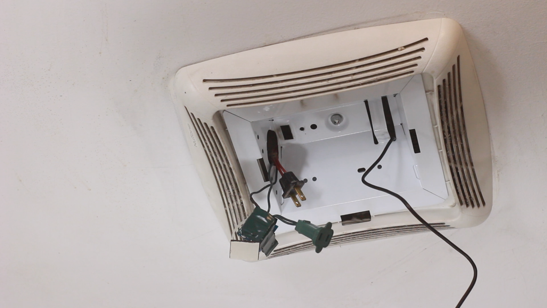
Step 4: Wiring It Up!


I had some Christmas light that had burned out and last year when all the LED were on sale I upgraded. I have a few sets of light laying around so I cannibalized the plugs from both ends. I spliced one of the wires together using solder and heat shrinkable tubing. The other wire I tined (solder) both ends but not together. Once it had cooled I trimmed them so that none of the metal would stick out. I then screwed them into the normal open (NO) and common (COM) terminal blocks.
I used some electrical tape to cover any of the exposed circuitry and leads.
I used a ziptie blocks and a Zip tie to secure everything to the compartment.
Step 5: Install


Install was really easy (for me).
As you can see my fan has 2 plugs under the plastic cover. One will be for the fan and the other will for usb power.
I plugged everything in and fed it through where the light once was.
Once I had it all wired in and powered up I gave it a test, and when it worked I installed the zip tie block.
Step 6: IT WORKS!

It worked first shot.
I had done a bunch of testing before be never hooked up to anything. So glad it worked and now my home automation has started!

Runner Up in the
Automation Contest 2017

Participated in the
Home Improvement Contest 2017


