

Introduction: Wolf : IoT Multi-Terrain Quadruped


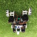

Step 1: Rover Mode
Step 2: Sensor Data to Watson IoT
Step 3: Materials


A) Mechanical Part
2x Aluminum Multi-Purpose Servo Bracket Two Pack(2x12 = $24)
2x Aluminum Long "C" Servo Bracket with Ball Bearings Two Pack (2x13 = $26)
2x Aluminum "L" Connector Bracket Two Pack (2x6 = $12)
Printed Parts ($10)
B) Electronics Parts
1x Raspberry Pi 2 ($30)
1x Pi Camera module ($8)
1x USB wifi adapter ($5)
1x Mini Maestro 18-Channel USB Servo Controller ($40)
1x Raspberry Pi motor hat ($22)
4x Pololu-Maestro 75:1 DC Micromotor ($15)
12x HobbyKing™ High Torque Servo ($9)
1x Turnigy 6V / 2300 mAH Ni-MH Rechargeable Battery ($10)
2x Micro Servo ($2)
1x Anker Astro E1 5200mAh ($20)
Optional part for more functionality
MPU9250 IMU ($20)
Lidar Lite 3 ($110)
Ublox GPS ($16)
Frame = $72
Electronics = $320
Total + tax + shipping = $400
Step 4: Printed Parts


A) Body
1x Body Plate Bottom
1x Body Plate Top
1x Front Shield
2x Side Shield
B) Internal Parts
1x Turnigy Battery Cover
1x Pi Stand
1x MPU Case
C) External Parts
1x Motor Stand
1x Lidar Stand
1x Camera Base
1x Camera Body
1x Camera Top
1x Camera Mount
1x Camera Cover
1x GPS Top
1x GPS Bottom
D) Leg Module
2x Leg
2x Leg Reverse
4x Wheel
4x Motor Hub
Note : If you wanted you can also 3D printed the all the Servo bracket that I listed in the material section if you don't want to buy them. I have makes 3D files for those part too. Look in the Servo Bracket.
Step 5: Constructing the Leg

So for the leg of the robot, I will divide this section into 3 part as describe: coxa, femur, tibia.
Step 6: Constructing the Leg : Coxa


- First take 2 aluminum bracket and joined them together as shown in the first pictures. Make sure that the bracket is secure tightly and they do not move around.
- Next, install a servo onto the bracket and secure them onto the bracket using 2 screws as shown in the third picture.
Step 7: Constructing the Leg : Femur


- Take two C Servo Bracket and connect them together with screws as shown in the first picture.
- Then connect the newly make femur to the coxa as shown in the second picture. Remember not to forget to put in the ball bearing or the leg won't move smoothly.
- Next, put in a servo on the empty bracket and secure it as shown in the third picture.
Step 8: Constructing the Leg : Tibia


- First, connect the motor to the wheel, just make sure that you already solder the 2 wires for powering before began this step.
- Next, add the motor hub to the motor as shown in the second picture. In addition, you can also cover the wire with heating tubing to make the wiring more organized.
- Then, added the entire section you just build onto the leg in such way that shown in the third and fourth picture.
- Make sure the motor is secured to the leg with a screw.
Step 9: Constructing the Leg : Tibia (continue)


- Take another servo bracket and connect it to the other end of the femur as shown in the first picture.
- Attached a servo into the empty bracket and secured it with screws.
- Then take the leg section that you just constructed and attached it to the lower leg as shown in the second and third picture.
- Finally, an entire leg should be finished. Repeat this until you have constructed four legs.
Step 10: Wiring

Before we begin the next step in building the robot, I am going to discuss wiring first since half of the electrical component is inside the robot so it an integral part of build the robot body.
- The Raspberry Pi is connected to an Anker Batter for power supply
- The Mini Maestro's is connected to the Raspberry Pi via USB for Serial Communication. The Maestro is power by a Turnigy Nihm battery. In addition, the Maestro is a servo driver so it connected to all the servo
- As for the IMU ( MPU 9250) and the Lidar :
- SDA to pin 3
- SCL to pin 5
- GND to pin 6
- VCC to pin 2
- For the GPS
- RX to pin 14
- TX to pin 15
- GND to pin 6
- VCC to pin 2
- For the Adafruit Motor Driver
- SDA to pin 3
- SCL to pin 5
- GND to pin 6
- Power to pin 1
Step 11: Building the Body


- Put the battery on the small square that is on the lower body
- Make sure the face with protruding rectangle is facing down.
Step 12:

- Need use the battery cover and put it on top of the battery. Secured this part using two screws
- In addition, put 2 more standoff to the side with height to the top part of the battery
Step 13:

- put the Raspberry Pi on top of the battery cover.
- Secure the Pi onto the standoff and battery cover using around 3cm standoff.
Step 14:

- Attached the Servo Stand on top of the raspberry Pi and secure it down onto the standoff with screws.
- Then attached the Mini Maestro onto the Servo Stand piece.
Step 15:

- Put the MPU9250 into the IMU case. This will be the IMU module.
- Attached the IMU into the Servo Stand piece. You can also use super glue to make sure it secure.
Step 16:


- Attached the two Side Shield on the along the two side of the robot
- Attached the Front Shield onto the front side of the robot.
- Attached the four leg onto each corner
- Finally, put the Top Plate onto each shield and use screws to secure it
Step 17:


- Put on the Anker battery as shown in the first picture.
- Next, place the motor driver on the on top of the Anker battery and secure it down to the two standoff as show in the second picture.
Step 18:

- Now place the Motor Driver Cover on top of the Motor Driver
- Put on the camera module and the GPS module.
Step 19: Setting Up Raspberry Pi 2

Getting The Raspberry Pi 2 Ready
- First, you need to have a Micro SD card and load the Raspian Wheezy Operating System(OS) in to the card. Here is an Instructables that I used to install the OS.
- Once you have inserted the Micro SD card into the slot on the Raspberry Pi 2. You have 2 option to start using the Raspberry Pi 2.
- Option 1 :
- SSH into the Raspberry Pi 2. This option doesn't require a keyboard and a monitor, but you must have an Ethernet cables . Follow this guide on how to do this.
- Option 2 :
- Plug your Raspberry Pi 2 into a monitor and connect a keyboard into the Raspberry Pi 2 USB port.
- Started your Raspberry and enter pi for username and raspberry for password. Now you should have access to your Raspberry Pi
- Option 1 :
- Once you have access to the Raspberry Pi, you need to enable the wifi to get thing rolling. Enter :
- sudo nano /etc/network/interfaces
- Enter the following text into the space :
auto lo

iface lo inet loopback
iface eth0 inet dhcp

allow-hotplug wlan0
auto wlan0


iface wlan0 inet dhcp
        wpa-ssid "ssid"
        wpa-psk "password"
- ssid is the name of your network. password is the password of your network
- press Ctrl+X to exit and save.
- Restart your Raspberry Pi and Wifi should be working.
- Type in : sudo apt-get update ( to update your system)
- If the update failed due to no connection. Try some other tutorial like SETTING WIFI UP VIA THE COMMAND LINE.
- If update was successful. Type in : sudo apt-get upgrade (this installed the new updated packet)
Step 20: Dowloading Node.js and Source Code

This part is to get the software for streaming and controlling the robot. Do the following step. Note, all the bold text are command line.
- Getting Node.js . Type in the following command
- curl -sLS https://apt.adafruit.com/add | sudo bash
- sudo apt-get install node
- node -v ( check node version, make sure that it is 0.12)
- Next we going to get the necessary Node.js library. Type in these command in your Raspberry Pi 2
- npm install serialport
- npm install socket.io
- npm install winston
- npm install express
- cd node_module
- Now, we going to get the streaming software
- sudo apt-get update
- raspi-config
- Choose Enabled Camera. It is Option 5
- sudo apt-get install uv4l uv4l-raspicam
- sudo apt-get install uv4l-webrtc
uv4l --driver raspicam --auto-video_nr --width 640 --height 480 --encoding h264 --framerate 20 --vflip yes --hflip yes (command to run the streaming software. Type in http://raspberrypi:8080/stream on your browser to test if the stream is working )
- Loading the robot code from github.
- git clone https://github.com/HackHusky/Wolf.git
- cd Fenrir
Now you should have everything that allow you to run the Fenrir software on Rapsberry Pi 2. To start the software do this :
- ./start.sh
Then put Raspberrypi.local:5000 on your browser to start control your robot.
Step 21: Software : Description

Wolf main software is similar to Husky , but with an upgraded User Interface(UI). In this section, I'm going to digress on some important files of the software. Wolf wireless control is design around using Wifi. Inside the robot software, there is a file called app.js. This is Wolf's webserver that uses your home Wifi and broadcast the signal throughout the entire network. After you started the robot and run the software, open up a browser and typed in raspberrypi.local:5000 and you should see a fully working UI with video streaming. The reason I use Wifi as opposed to Bluetooth or Radio Control(RC) control is because it had an easy way to integrate video streaming.
Folder Structure
The below diagram is a presentation of the files structure in the main software. The two important files in the software folder is the app.js and client.js . I will digress more on these two files in the next section.
Main Folder
app.js (server side )
start.sh (bash script to run node and camera progarm)
Public (web interfaces folder)
index.html
js (javascript folder for the web interface)
client.js (client side)
socket.io.js (websocket libary)
Servo.js
LIDAR.js
MPU9250.js
dist(resource for webpages)
build(boostrap file)
pages(chart and icons asset)
Step 22: Software: App.js
App.js is a local server written in javascript and it used websocket to communicate with other device through wifi.
The following code create an object to use function from within the socket.io library and then tell the app to listen to port 5000.
var app = require('http');
createServer(handler);
io = require('socket.io').listen(app);
url= require('url');
fs = require('fs');
app.listen(5000);
The next part of the code is simply forwarding the content in public through the wifi so that you can communicate with it via ip address.
// Http handler function
function handler (req, res) {
    // Using URL to parse the requested URL
    var path = url.parse(req.url).pathname;
    // Managing the root route
    if (path == '/') {
        index = fs.readFile(__dirname+'/public/index.html',
            function(error,data) {
                if (error) {
                    res.writeHead(500);
                    return res.end("Error: unable to load index.html");
                }
                res.writeHead(200,{'Content-Type': 'text/html'});
                res.end(data);
            });
    // Managing the route for the javascript files
    } else if( /\.(js)$/.test(path) ) {
        index = fs.readFile(__dirname+'/public'+path,
            function(error,data) {
                if (error) {
                    res.writeHead(500);
                    return res.end("Error: unable to load " + path);
                }
                res.writeHead(200,{'Content-Type': 'text/plain'});
                res.end(data);
            });
    } else {
        res.writeHead(404);
        res.end("Error: 404 - File not found.");
    }
}
In addition we also put the code to control the servo inside app.js. First , you need to create an object for the mini-maestro library like socket.io.
var PololuMaestro = require("pololu-maestro");
var maestro = new PololuMaestro("/dev/ttyACM0");
Then you can use the function inside the mini-maestro library as follow.
// Initiate communication with the servo controller
maestro.on("ready", function() {
 console.log("connection made");}
//Set the speed of servo at pin 0 to 60
maestro.setSpeed(0, 60);
// Set the angle ( you write in PWM value) at pin 0
maestro.setTarget(0, 1200);

//Example function
function LiftForward(){
    maestro.setTarget(12, 600);
}
Next we need to include a portion of code to call these function when we get the data from the communication side that they want to run a certain function.
// Check for signal being sent
io.sockets.on('connection', function (socket) {
  //If signal is CR, then run CameraRight();
  socket.on('LF', function(data) {
      console.log("LegForward");
      LiftForward();
  });

}
Step 23: Software: Client.js
client.js handle all the input that the user do in the web intertfaces and send it back to the app.js so it interpret those command and execute the proper function. Here is a simple example of the code that need to in client.js
//Check to see if the keyboard is press
$(document).keypress(function(e){
//If the letter K was press, send the string LF back to the server
 if(e.keyCode == 107){
        socket.emit('LF');
    }
}
There are a lot more in the client.js ,but all other command was just simply reuse the above template to interact with other keyboard stroke to send different command.
Step 24: Software : Servo.js
I am going to talk briefly about how to control the servo for testing and creating leg movement here in case you want to create your own movement algorithm . There two main ways to test out and model the servos movement before you fully implement it.
The first method to is to connect the Mini Maestro Servo Controller directly to the your computer and use the Maestro Control Center Software to create leg movement. This is the easier method out of the two.
The second method is control the servo via Node.js in the Rapsberry Pi 2. In essence, the Raspberry Pi 2 use a maestro library ( https://github.com/omcaree/node-pololumaestro.git) created by omcaree to communicate with the Mini Maestro Servo Controller. You must have all the necessary Node.js library that i mention in Getting the Raspberry Pi 2 Ready in order for this to work. Below is an example javascript code using Node.js to control the servo.
<
//Example code on how to user Node.js Mini Maestro Servo Controller library
//This code move the servo back and forth indefinitely

var PololuMaestro = require("node-pololumaestro");// needed to use servo library
var maestro = new PololuMaestro("/dev/ttyACM0");// input your USB port name here

maestro.on("ready", function() { //initiate communication with the Servo Controller
 console.log("connection made");
 maestro.setSpeed(0, 100);// set servo at pin 0 to speed 100.
});

var Delay  = 500;   	// our delay timer
var Multiplier = 0;	//delay multiplier

while(1==1){      //loop
setTimeout(function(){	// simulate delay
 maestro.setTarget(0, 800);// move servo at pin 0 clockwise
 }, Delay*Multiplier);// will execute  maestro.setTarget(0, 800); after 500 ms
Multiplier++;	// increment multiplier so next delay will be 1000ms

setTimeout(function(){
 maestro.setTarget(0,2300); // move servo at pin 0 counter clockwise
}, Delay*Multiplier);//will execute  maestro.setTarget(0, 2300); after 1000 ms
Multiplier++;// increment multiplier again so next delay will be 1500ms
}
What I usually do is simulate the leg movement in the computer first. This will give you a sequence of servo positions in microsecond. From there i look at all the number and see if i can com up with an algorithm to implement it in Node.js.
Step 25: Software: Lidar
I choose to digress the Lidar software because it fairly short and simple code that explain how the I2C communication protocols work. I2C and Serial/UART communication protocol are the probably the 2 most important type of communication protocol in robotics. This is how the main board/driver board control with different sensor, motor, servo. On a hobbyist level, you probably won't have to worry too much about this since there library already made for them. However, if you want to go deep in robotics then you need to know these things.
So for the Lidar Lite, there is a C library to interact with it but there no Node.js library. So you need to make one for the Lidar.
First, go and read the documentation.
So that was a lot of information but there only a few thing you need to look for :
Lidar address : 0x62
Lidar Control Register : 0x00
Lidar Distance Register High byte (MSB) : 0x0f
Lidar Distance Register Low byte (LSB): 0x10
The Lidar address is simply just to tell the Pi where the Lidar is, the register is how you control the Lidar. some register is read only, some is write only, and some can be both. In our case, the control register is write only and the two distance register is read only
Now for the code :
const Lidar_Address             = 0x62;
const Lidar_Control             = 0x00;
const Lidar_Distance_HighByte   = 0x0f;
const Lidar_Distance_LowByte    = 0x10;

//library for communicating with i2c device
var i2c = require('i2c-bus'),
  i2c1 = i2c.openSync(1);

//creat an 2 array of 8bit
var Byte = new Uint8Array(2);
var Distance = 0;

setTimeout(function(){
	//start taking a single measurement
	i2c1.writeByteSync(Lidar_Address,Lidar_Control,0x04);
		setTimeout(function(){
				//read in the data
			    Byte[0] = i2c1.readByteSync(Lidar_Address,Lidar_Distance_HighByte);
			    Byte[1] = i2c1.readByteSync(Lidar_Address,Lidar_Distance_LowByte);
			    // combine date together
			    Distance = new Int16Array([Byte[0] << 8 | Byte[1]])[0];
			    outputting it
			    console.log("Distance: "+Distance+" cm");
			    return Distance;
			}, 20);
        }, 20);
For this Lidar, you need to set a delay after initiating taking the measurement. Javascript don't have delay function, but you can use setTimeout to execute a certain command after x amount of time.
Step 26: Software : Getting Node-Red

Type in the following command :
sudo apt-get install nodered
If this install successfully you can skip to the next step, if you have this error "no nodered package found" then make sure the your node.js version is 4.0 or higher and type in the following command :
sudo npm install -g --unsafe-perm node-red //install node red
cd $HOME/ .node-red // go inside node red
npm install node-red-contrib-ibm-watson-iot // instal watson iot output
cd .. // back to home
node-red //start node red
You should see an ip address when node red is running : Example
127.0.0.0.1:1880
1880 is the port number that node red is running on
Simply type in the "Pi IP address:port numer "
so for mine I would do : 192.168.1.141:1880
Step 27: Software : Iot Watson With IMU Sensor(MPU9250)
Here i am going to show you how to use Node-Red to send your sensor data to the IMU.
First create this javascript to output the pitch and roll
var mpu9250 = require('mpu9250');
// Instantiate and initialize.
var mpu = new mpu9250();
if (mpu.initialize()) {
  var values = mpu.getMotion9();
  var pitch = mpu.getPitch(values);
  var roll = mpu.getRoll(values);
  console.log(pitch+" "+roll);
}
Step 28:

Next, run Node-Red and go to it web interfaces. First, drag the Inject square under the Input tab into the flow. Double click on the Inject square. Enter into the field as shown in the picture above. The field option that I choose pretty much made the Inject act as an interval function that send information every 3 seconds
Step 29:


Now, drag the Exec square from under the Advance tab. Connect the Inject to the Exec. Double click on the Exec and enter information into the field as shown in the second picture. The Exec square function is to simply execute the test.js by calling "node test.js"
Step 30:


Next, drag the Function square from under the Function tab and make a link from the Exec to the Function. Double click to edit the Function square and input the following code
var orientation = msg.payload.split(" ");
msg.payload={'d':{'pitch':orientation[0],'roll':orientation[1]}}
return msg;
This simply takes the output from the test.js and reformated the string so that the information can be send to the Watson IoT.
Step 31:


Finally, drag the Watson IoT square from under the output and make a connection from Function to the Watson IoT. Now click deploy then click the little square on the Inject. Now everything should be running. To view the data as a graph is Watson IoT, you need to double click on the Watson IoT square and click on Quickstart Id square as shown in the second picture. It will take you to the Watson IoT's web page with graphs of your data.

Participated in the
Design Now: 3D Design Contest 2016

Participated in the
IoT Builders Contest

Participated in the
Arduino Contest 2016


