

Introduction: LEDs


As you can see from this extreme closeup of an LED pictured above, it is actually quite different from a light bulb. LED is an abbreviation for light emitting diode. It is a special type of electronic component that emits photons when electricity flows through it in the right direction. Over the last two decades, LED technology has changed and improved dramatically. LEDs now come in so many countless types and configurations, it would be impossible to survey them all in this class. On account of their versatility and pervasiveness, you could say that LEDs currently shine brighter than all other lights. Let's see why.
Step 1: Light Bulbs Vs. LEDs

An LED is nothing like a classic incandescent light bulb. For starters, a light bulb heats up a filament to a very high temperature, which creates heat, and forces metal to emit light. This requires a lot of energy and a big power source. On the other hand, LEDs emit photons when electrical current passes through a semiconductor. The semiconductor material generates little to no heat during this process. This draws very little energy, and does not require much power at all.
Additionally, a light bulb is non polarized. This mean that it will light up regardless of which way a DC electrical current is attached to its terminals. An LED on the other hand has a right and wrong way to connect electricity. If a DC current is wired in the wrong way, the LED will do nothing.
Also, light bulbs are omnidirectional in light production, whereas LEDs are designed to emit light in a beam at a certain angle
Step 2: Understanding Diodes

In order to understand LEDs, you need to first understand what a diode is.
A diode is an electronic component that allows electricity to flow through in one direction, and all but stops it from flowing the opposite way.
A diode's primary role is to route electricity within a circuit. This is extremely useful for preventing an electrical signal from taking unwanted or unexpected routes or flowing in the wrong directions.

All diodes are polarized. This means they have an anode (positive side) and cathode (negative side). You can tell the difference because the cathode has a little line painted around it.
What this means is that electricity can only flow through in one direction. A positive voltage should be connected to the anode and the cathode should be connected to ground.

If you look very carefully inside of an LED, you will be able to see its anode and cathode. The thin wire bond attached to the anode bridges across to the center of a small reflective bowl attached to the cathode. In the center of the reflective bowl sits the semiconductor die. When current flows from the anode to the cathode, the semiconductor material emits photons, reflects off the bowl, and is further amplified by the resin material of the LED.
Step 3: How Diodes Work
Before we dive too deep into LEDs, it is important to understand a bit more about how the anode and the cathode actually work. While this is going to get a little bit technical, it will be important for understanding LEDs later on.

A diode consists of a PN junction made of P-type silicon and N-type silicon separated by a depletion region. The depletion region acts like an insulator. Put simply, the P-region is connected to the anode, and the N-region is connected to the cathode. The depletion region sits between the two.

When the P-region is connected to ground and the N-region is connected to a positive voltage, the depletion region actually grows in size. This ensures little to no electricity is able to flow through the diode between power and ground. In this configuration the diode is considered reverse biased.

When a positive voltage is applied to the P-region and the N-region is connected to ground, the depletion region all but disappears and allows electricity to flow. In this state the diode is considered forward biased.

In order to overcome the depletion region, a little bit of voltage must be sacrificed. This is called the voltage drop. In a standard silicon diode like the one pictured this is typically 0.7V. However, and LED can have a much higher voltage drop. A typical voltage drop in an LED is 1.8 to 3.3 volts, and this varies by color.
In other words, if you have a 5V signal and it passes through an LED with a 1.8V drop, the voltage that comes out the other end will be 3.2V. It can fluctuate above or below this value depending on the type of LED.
This drop in voltage is what is referred to as an LED's "Forward Voltage."
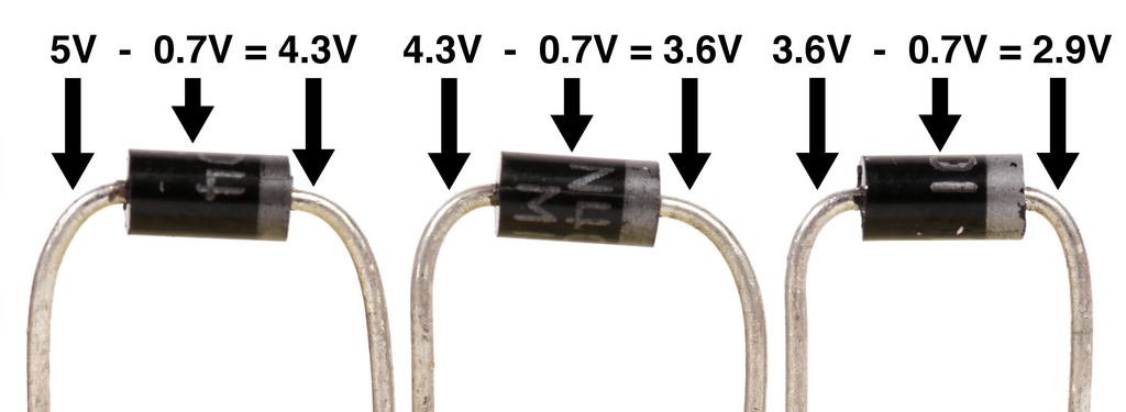
If you have three diodes in series, you will lose 0.7V through each diode and the voltage at the far end of this chain will be 2.9V. If you consider LEDs offer a voltage loss more than double this amount, connecting three in series would add up to a significant loss, and is the reason LEDs should be connected in series sparingly.

While diodes charge a toll to cross the depletion region in the form of voltage, they offer no real resistance. If you put only diodes in a circuit without a load to use up the electricity, it will virtually look like a short circuit and draw as much current as the power supply is able to provide. Since that is likely higher than the diode's maximum current rating, it will release the diode's magic smoke.
Step 4: Current Limiting Resistors

Since an LED is basically a diode and offers no resistance in a circuit, it typically requires a component called a resistor (that offers a fixed amount of resistance) in series with it.

This prevents the LED from being shorted and - given enough current - literally exploding.

As a general rule of thumb, a 470 ohm resistor should be more than enough to protect just about any low-power LED.

However, should you want to calculate the proper resistor for maximizing brightness, you can calculate this by using this equation. Even more simply, you can search online for "LED resistor calculator."

For instance, given this LED with a 3V voltage drop (forward voltage), 20mA operating current, and a 9V source, we can calculate that the proper resistance is 300 ohms. However, that is the absolute minimum resistor, and since resistors tend to have a tolerance range, it is best to increase the value a little to be on the safe side. It is safe to say then that a 330 ohm resistor should do the job. However, you don't want to increase it too much because the more resistance there is, the dimmer the LED becomes.
Step 5: Understanding Resistors

Resistors have their value printed on them in color codes. To begin with, you can probably just get away using an online resistor calculator to determine their value. If you chose to go this route, you may skip this section.
However, if you are curious on how to decipher them yourself, read on. I'm about to show you.
Telling its current rating can typically be established by the size of the resistor. This is something you will figure out intuitively in time, and not remarkably important for the kind of low-current circuits you will be working with when getting started.
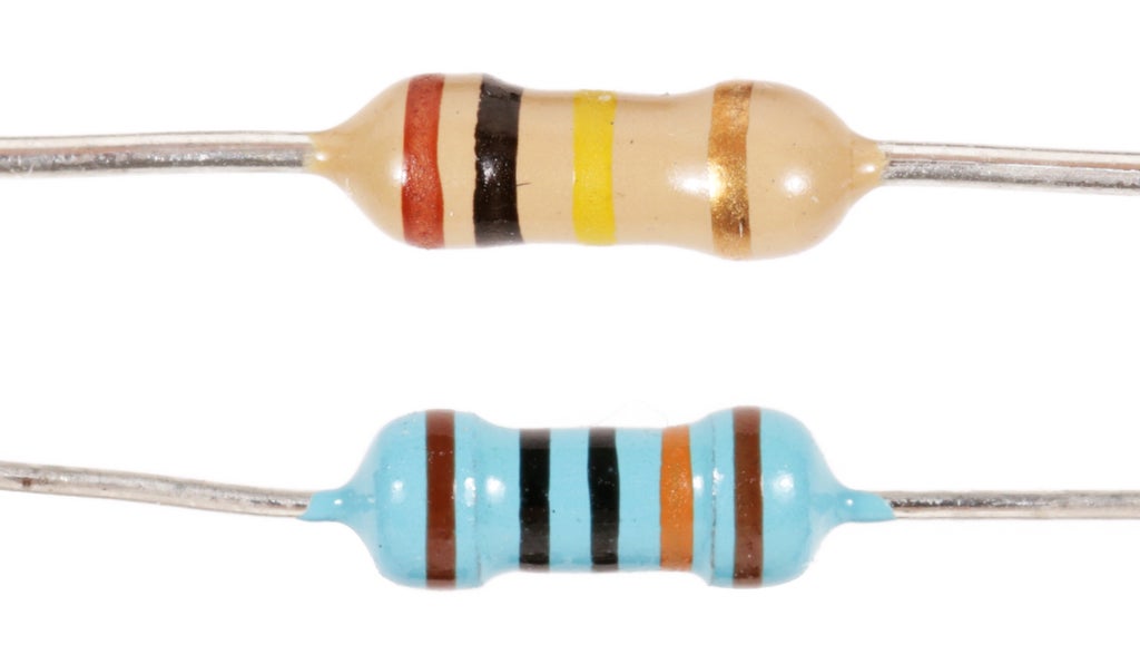
Determining how much resistance a resistor offers is a little trickier and can be established by deciphering the colored stripes from left to right towards the tolerance marking. You will typically see four stripes, but you may also encounter resistors with five.
Resistors with four stripes are the most common. These will likely be the type you are working with most.
When reading a resistor with four stripes, the first two stripes are combined together to form a number between 1 and 99. The third marking is the multiplier. The last marking determines the tolerance, which is basically the accuracy of the resistor and not typically important to know about when working with LEDs. If you would like to learn more, check out the Resistors lesson in the Electronics Class.

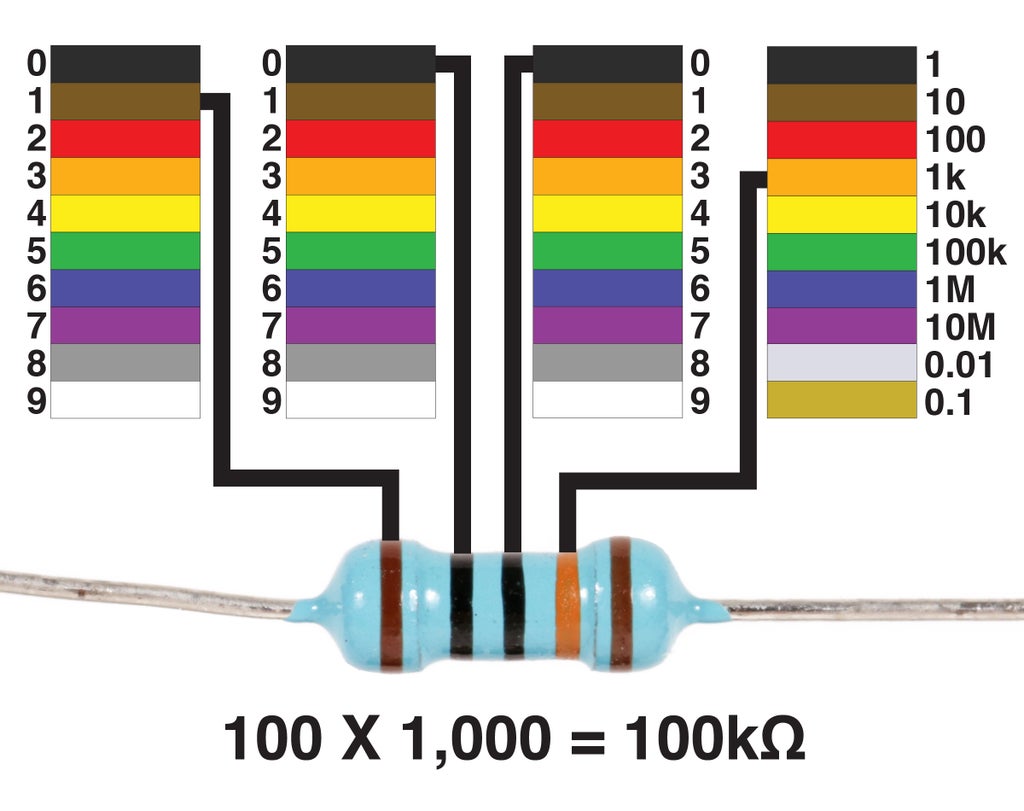
For instance, in the following example, the first two lines represent 1 and 0, which is combined together as the number 10. This is then multiplied by 10,000 (which is the multiplier). The result is 100,000Ω.
However, when a resistor is 1,000 or more ohms, we measure it in kilo-ohms. A kilo-ohm is basically equal to 1,000 ohms. So, 100,000Ω is shortened to 100kΩ. Basically, it is 1,000 ohms times 100. All we are essentially doing is removing three zeros from the number, and replacing them with with k.
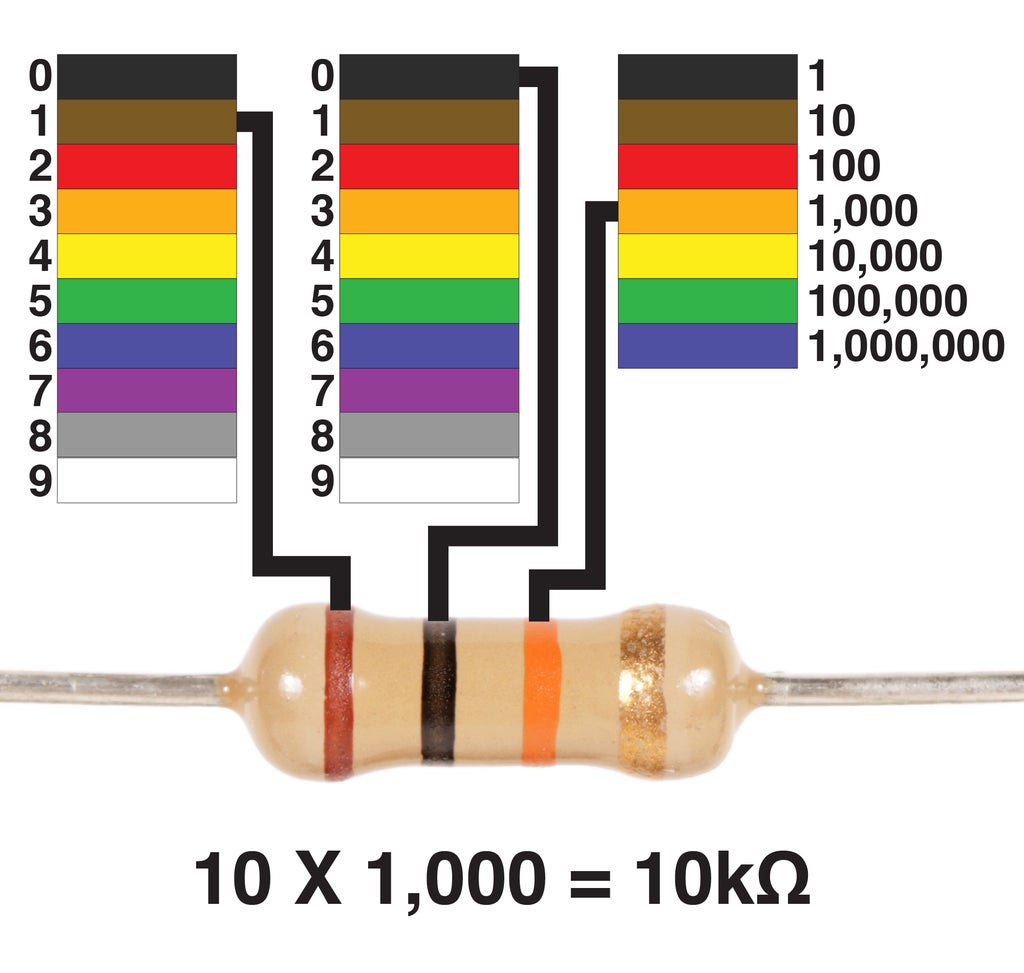
If that was confusing, let us look at another example. This resistor has the same initial number of 10, but a multiplier of 1,000. When multiplied together, these numbers yield a resistance of 10,000Ω or 10KΩ.

Now, let's say the first two numbers were to change, and the multiplier were to decrease. In this example, the first two colors when combined create the number 68. When multiplied by 10, we get the number 680. Since 680Ω is less than 1,000, we just call this resistor 680Ω.
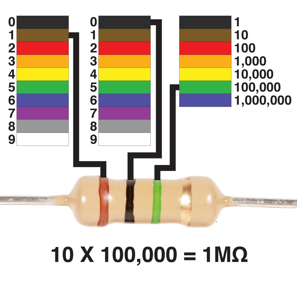
One last thing, if there is a million or more ohms, we then measure in mega-ohms. For example, this resistor is worth 1,000,000Ω. This is shortened to 1MΩ.
Resistors with 5 stripes are a little less common, but just as easy to read. Let us briefly consider how to read them. Like the 4 band resistor, you first find the tolerance marking on the far edge, and then read left to right towards the marking.
However, where they differ is in that the first three stripes get read as a single number, and the fourth stripe is the multiplier. So, in this case, we can determine the first number is 100 and it gets multiplied by 1,000, giving us a resistance of 100K.
The fifth stripe is the tolerance marking.
Step 6: Deciphering LEDs
Like resistors, diodes also need to be interpreted based on their packaging.
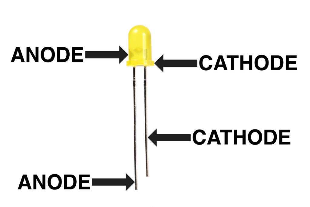
There are typically three ways to tell a standard 5mm LED's anode from its cathode.
1) The leg connected to the anode is typically longer than the one connected to the cathode.
2) The body of the LED typically has a flat spot on the cathode side.
3) If you look inside the LED, the little metal bit connected to the anode lead is much smaller than the cathode.
Step 7: Types of LEDs
There are so many different types and form factors of LEDs at this point, it is hard to keep up.

LEDs come in different shapes and sizes. The 5mm domed is the most common, but you are liable to also find them in 3mm domed, 10mm domed, rectangle, oval, and square (to name a few).

LEDs also come in many different colors. Often the plastic is tinted to indicate what color they are. However, clear LEDs are deceptive in that you might assume they glow white, but can actually glow a host of different colors.

LEDs have different levels of brightness that are typically measured in MCD (millacandella). One thousand millacandella is equivalent to the brightness of one candle. So, an LED like the one pictured above with an intensity of 6,000mcd is equal to the brightness of 6 candles. It is not uncommon to also see extremely bright high-power LEDs to be measured in Lumens - another unit of light measurement - or Watts.

LEDs have different viewing angles, or beam widths. What this means is that the visible brightness of the LED seems to decrease when you are looking at the LED from and a spot outside of its ideal viewing angle. This angle also determines the size of the spotlight created by the LED. The viewing angle on an LED can vary widely.

LEDs also draw different amounts of power. In fact, some high power LEDs draw so much power that they are mounted on metal heatsinks to dissipate heat. While LEDs such as these tend to be very bright, they sometimes require special constant current circuitry to drive them.

LEDs can come grouped together into display modules. With these LED dot, bar, and 7-segment numerical displays, each individual light-up segment is a discrete LED. For instance, the 8X8 matrix on the left actually has 64 separate LEDs inside of it.

Multicolor or "RGB" LEDs are individual red, green, and blue LEDs built into a single LED package. Typically, each color has its own anode, and they all share a common cathode. By varying the voltage on each anode, the amount of red, green and blue light being emitted can be varied. By mixing these lights together, you can create nearly any color in the visible light spectrum. These LEDs are miniaturized and attached to the multicolor LED strips we will encounter in the next lesson.
Step 8: Applying Power to an LED
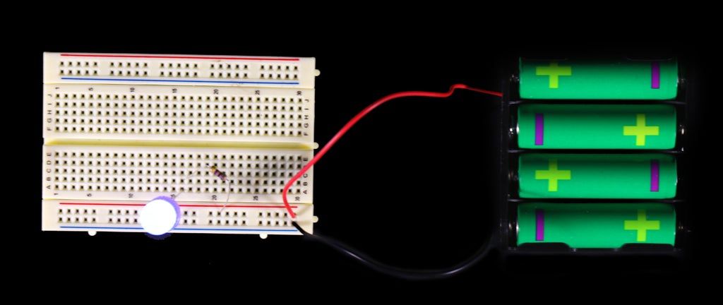
To power an LED, you simply connect it to a battery pack in series with an appropriate current limiting resistor. As a general rule of thumb, a 470 ohm resistor is typically more than enough resistance for any 5mm LED that is being powered with 9V or less.
Step 9: Connecting LEDs Together

If the LEDs are all the same, they can easily be put in parallel to your heart's content - well, within reason. You need to keep in mind how much current they are drawing in relation to how much current your power supply can provide.

If you want to put different colors in parallel, each one needs it's own current limiting resistor. This is because each color of LED has it's own forward voltage, and forward voltages change depending on the type of LED and who manufactured it. It's important to always look up the forward voltage and calculate the correct resistance.
For example, if you have 3 blue LEDs and 1 red LED wired in parallel, the three blue LEDs can share a single resistor, and the red one requires it's own different resistor. This is to ensure you don't accidentally destroy the red LED by giving it too much current, or under-power it by giving it too little.
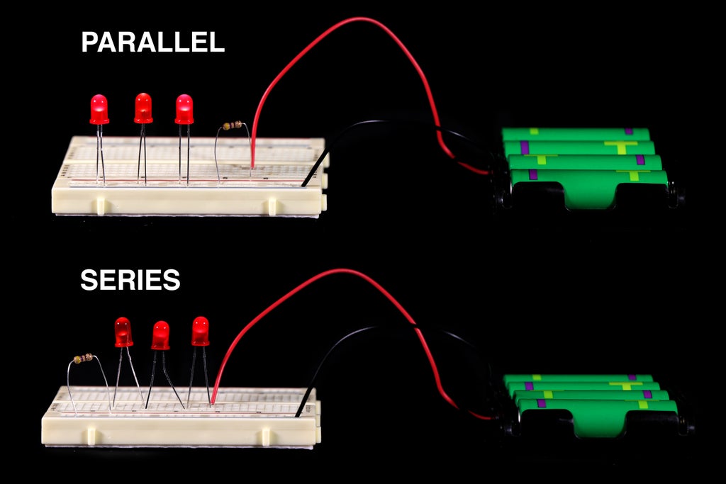
You can place LEDs in series, but every time you do so, there is a voltage drop across the LED. This changes the amount of resistance required. For instance, if you calculate that one single LED requires a 220 ohm resistor, and then put 3 LED in series with this resistor, it is going to have too much resistance and be fairly dim.
You need to decrease the resistance to maintain brightness because of the voltage loss throughout the circuit. With the formulas you already have learned for calculating voltage drops and the proper resistor, you should be able to figure this out. Or - you can do as I do - and use this online calculator.
Step 10: Manually Control LEDs

An LED can be turned off using a switch placed in series between it and the power supply. This does not have to be just a basic toggle switch. You can explore specialty switches such as tilt or, magnet switches. You can learn all about switches in the Switch lesson of the Electronics class.

Adjusting the brightness of an LED can be adjusted quite simply using a 1K potentiometer in series with its current limiting resistor. This adjustable knob will sweep the resistance between 0 and 1K ohms. The addition of extra resistance will cause the LED to dim as the resistance increases.
We can also replace the potentiometer with any variable resistor, such as a photocell to make it light controlled.
To learn more about potentiometers and photocells, once again, I recommend checking out the Resistor Lesson of the Electronics Class.
Step 11: Arduino Control (advanced)
If you already have an understanding of Arduino, controlling LEDs is easy.
To blink the on-board LED connected to pin 13, simply open and upload the following example code:
01.Basics --> Blink
If you know how to use Arduino, chances are you have already done this a long time ago.

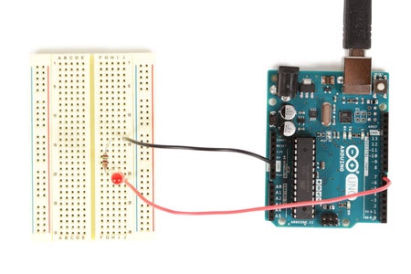
If you would like to blink an external LED, insert an LED into a breadboard. Connect a 150 ohm resistor in series with the LED's cathode.
Using a black solid core wire, connect the opposite end of the resistor (the side not connected to the LED) to ground on the Arduino.
Using a red solid core wire, connect the LED's anode to digital pin 7 on the Arduino.
Finally, go to the "Blink" example code and change all the number 13s to the number 7. By doing this, you are simply changing the digital pin that is being pulsed on and off from 13 to 7 in order to match the circuit you built on your breadboard.

Aside from blinking an LED, we can also make one fade. To do this we need to use a PWM pin. The PWM pins are special digital pins on the Arduino that allow for an analog-like output that simulates an output voltage between 0 and 5V. They are all labeled with a ~ in front of the pin number.
PWM stands for pulse width modulation. Put simply, PWM is toggling a pin on and off so fast that it gives the appearance of dimming the LED.
A dim LED glowing at 1/4 brightness means that the signal being sent to it is toggled off much more than it is toggled on. For instance, it is turned off 75% of the time and turned on 25% of the time. A brighter LED at 3/4 brightness is receiving a PWM signal that is the opposite. So it would be on 75% of the time and off 25%. The thing is, it is happening so fast, you don't see that it is being turned on and off, but only experience the LED as being slightly dim.
Anyhow, if you want to fade the LED, from the examples menu select:
03.Analog --> Fading
Once done, swap the wire connected from digital pin 7 to digital pin 9, and upload the code to your Arduino.
The LED should now fade in and out.


